Showing posts with label Fuel Injection. Show all posts

Saturday, 9 January 2021

Characteristics of Diesel Fuel

 Diesel is obtained by graduated distillation of crude oil. The boiling point range of diesel fuel can vary from 180⁰C to 370℃ depending on the hydrocarbons. Diesel ignites at approximately 350℃ which is much lower than that of gasoline which ignites at approximately 500℃.

Quality and Grading Criteria of Diesel:

In Europe, the standard for diesel fuels is EN 590. The U.S. standard fir diesel is ASTM D975. High quality diesel fuel is characterized by the following features:

  • High Cetane Number
  • Relatively low boiling point
  • Narrow density and viscosity spread
  • Low aromatic compounds content
  • Low sulphur content
  • Good Lubricity
  • Absence of free water
  • Limited pollution with particulate matters

Cetane Number:

The Cetane Number (CN) indicates the quality of ignition of diesel fuel. The higher the CN, the greater is the ignition capacity of the fuel. As we know, diesel engines do not employ spark plugs to ignite the fuel, the fuel must ignite spontaneously and without any ignition lag.

CN 100 is assigned to n-hexadecane (cetane), whereas CN 0 is assigned to methyl naphthalene. As the number suggests, n-hexadecane ignites very easily, and methyl naphthalene ignites very slowly. Diesel fuel comprising of 55% cetane and 45% 𝝰-methyl naphthalene has a cetane number of 55.


CN in excess of 50 is desired for smooth running of the engine and low emissions. High quality diesel fuels consists of a higher proportion of paraffins with high CN ratings. Presence of aromatic compounds in the fuel can reduce the ignition quality.

Cetane Index:

Cetane index is another parameter which controls the ignition quality of a diesel fuel. It is calculated on the basis of fuel density and various points on the boiling curve. This does not take into account the impact of cetane improvers on ignition quality. Fuels whose cetane number has been increased by cetane improvers respond differently during combustion process than fuels with the same natural cetane number.

Nitric acid esters or alcohols are commonly used as cetane improvers. They shorten ignition lag and also reduce noise and emissions during combustion.

Boiling Range:

The boiling range of a diesel fuel depends on its composition. Boiling range is the temperature range in which the fuel vaporizes. A low initial boiling point is suitable for cold weather, but it also means lower CN and it results in poor lubrication leading to wear and tear. for this reason, the initial boiling point should not be too low.

A diesel fuel with higher final boiling point can result in increased soot production and nozzle coking (chemical deposition deposits of not easily volatized fuel on the nozzle cone and deposits of combustion residue). For this reason, the final boiling point should not be that high. The ideal boiling point would be 350℃.

Cold Flow Properties (Filtration limit):

Precipitation of Paraffin at low temperatures can result in fuel filter blockage, ultimately leading to interruption in fuel flow. The cold flow properties are assessed by means of filtration limit (Cold Filter Plugging Point (CFPP)).

To assist the flow of fuel in winter, polymer substances can be added as flow improvers. Although it cannot prevent the precipitation of paraffin crystals from the fuel, it can significantly reduce their growth so that fuel can still pass through the filter.

Flash Point:

Flash point is the temperature at which the fuel emits sufficient quantity of vapor to allow a spark to ignite the air-vapor mixture above the fuel surface. The flash point of diesel is over 55℃. Flash point determines the hazards to be taken unto consideration while transporting fuel. It should be noted that even a gasoline amount of less than 3% if mixed with diesel, it is sufficient to lower the flash point to room temperature.

Density:

The use of fuels with wide range of densities results in variations in air-fuel mixture ratios due to fluctuations in calorific value. The energy content of diesel increases if its density increases. Higher density type fuels can result in better engine performance, but also higher soot emissions.

Viscosity:

Viscosity is a measure of a liquid's resistance to flow due to internal friction. Higher the viscosity, higher will be the resistance to flow. There may be leakage of fuel in the injection pump if the viscosity is too low. Biodiesel, which has a much higher viscosity, causes a higher peak injection pressure at high temperatures in non pressure regulated injection systems (unit injection system). High viscosity also affects the spray pattern from nozzles due to the formation of larger droplets.

Lubricity:

The hydrogenation process reduces the sulphur content of the fuel, but is also removes the ionic components of the fuel which helps in lubrication. As a result, the hydrogenated fuel started to wear injection pumps. Lubricity enhancers are added to the fuel to enhance lubrication.

Lubricity is measured in a High Frequency Reciprocating Rig. A fixed clamped steel ball is ground on a plate by fuel at high frequency. The amount of wear on the ball is measured as Wear Scar Diameter (WSD) and is measured in µm. For a diesel fuel complying with European standards, its WSD must be ≤ 460 µm.


Fatty acids, fatty acid-esters or glycerin can be added to enhance the lubricity of the fuel. Biodeisel is also a fatty acid-ester, so if diesel fuel already contains a proportion of biodiesel, then no other lubricity enhancer is required.

Sulphur Content:

Diesel fuels naturally contain sulphur and the amount of sulphur depends on the quality of crude oil and components added during refining process. In particular, crack components usually have high sulphur content. As already stated above, sulphur is removed by hydrogenation process. 

Removal of sulphur helps in reducing sulphur dioxide emissions along with soot emissions. Moreover, presence of sulphur can poison the active catalyst surface present in catalytic converters. Since 2009, sulphur free fuel (sulphur content of less than 10 mg/kg) is allowed in the market.

Water in Diesel Fuel:

Even a small amount of water can damage the fuel injection pumps in a short period of time. Diesel from refineries often do not carry any amount of water, but water can enter fuel tank due to condensation of the air. For this reason, water separators are a mandatory equipment in any vehicle fuel supply system.

Friday, 8 January 2021

Combustion Chambers for Diesel Engines

 The shape of a combustion chamber helps in determining the quality of combustion and therefore the performance and exhaust characteristics of a diesel engine. Appropriate design of combustion chamber combined with piston action produces whirl, squish and turbulence effects that are used to improve the distribution of fuel and air inside the combustion chamber.

The following technologies are used in diesel engines:

  • Undivided combustion chamber for Direct Injection (DI) engines
  • Divided combustion chamber for Indirect Injection (IDI) engines
Between these two, undivided combustion chamber is predominantly used in vehicles due to their more fuel savings and lesser noise and vibration compared to the divided ones.

Undivided Combustion Chamber (DI):

The direct injection process involves injecting the fuel directly into the combustion chamber. The combustion chamber also relies on the shape of piston crown. Fuel atomization, heating, vaporization and mixing with the air must take place in rapid order.

During the intake and compression strokes, special shape of the intake port in the cylinder head creates an air vortex inside the chamber. Of the combustion chamber designs, the most widely used at present is the w piston crown recess.


The design of a combustion chamber must also ensure even distribution of the fuel inside the chamber so that rapid mixing of air and fuel can take place. A multi-hole nozzle is used in the direct injection process to achieve better atomization of the fuel. The pressure required for direct injection is pretty high at 2200 bar.

In practice, there are two types of direct injection:

  • Systems in which mixture formation happens by specifically created air-flow effects
  • Systems which control mixture formation virtually by means of fuel injection and largely avoid any kind of air-flow effects
In the latter case, no effort is wasted in creating air turbulence and therefore it helps in more effective cylinder charging and smaller gas replacement losses. However, it demands better nozzle positioning, higher number of nozzle jets and higher intensity of injection pressure in order to provide effective air-fuel mixture.

Direct Combustion Chamber:

As already mentioned, indirect injection engines are far less economical and noisy, along with higher exhaust gas emissions compared to the engines with direct injection technology. As a result, direct combustion chambers are rarely used.

There are two types of processes with direct combustion technology:

  • Pre-combustion chamber system
  • Whirl chamber system
Pre-Combustion Chamber system:

In the pre-chamber system, fuel is injected into a hot pre chamber recessed into the cylinder head. Pre chambers are much smaller in size compared to the main combustion chamber. The fuel is injected via a pintle nozzle(1) at a relatively lower pressure up to 450 bar. To make sure fuel is impartially burnt, only a small amount of air is supplied to the pre combustion chamber. A specially shaped baffle(3) is positioned at the centre of the pre combustion chamber. The injected fuel strikes the baffle and mixes thoroughly with air.


The partially combusted fuel/air mixture is sent to the main combustion chamber via a connecting channel(4), where it mixes with the available air and burns rapidly. The ratio of pre combustion chamber volume to the main combustion chamber volume is approx. 1:2.

A glow plug(5) is positioned on the lee side of the air flow. A controlled post glow period of up to 1 minute after cold start can help in improving exhaust gas characteristics and reduce engine noise during warm up period.

Swirl Chamber System:

In this process, combustion is initiated in a separate chamber (swirl chamber) that has approx. 60% of the compression volume. The spherical and disc shaped swirl chamber is linked by a connecting channel to the main combustion chamber at a specific angle.


During the compression stroke, air entering via connecting channel is set in a swirling motion. The fuel is then injected so that the air swirl penetrates perpendicular to its axis and meets a hot section of the chamber wall on the opposite side of the chamber.

As soon as combustion starts, the air fuel mixture is delivered under pressure to the main combustion chamber where it mixes with the remaining air. Since the cross section of the connecting channel between swirl chamber and main combustion chamber is larger than the one in the pre-combustion chamber, the gas flow losses are relatively lower in swirl chamber design. This helps in higher internal efficiency and lesser fuel consumption. However, the combustion noise is higher in swirl chamber design.


Thursday, 7 January 2021

Bosch Diesel Fuel Injection

 In 1922, Robert Bosch embarked on a journey to develop accessories required for a diesel engine (fuel injection pumps and nozzles). These pumps had to withstand several hundred atmospheres and nozzles had to have quite fine outlet openings in order to atomize the fuel droplets.

The fuel injection pump should be capable of producing high pressure and also inject small amounts of fuel so that the engine can operate even at low idle speeds. For full load operations, the fuel quantity should be increased by four to five times.

Development of Fuel Injection Pump:

Different pump designs were tried out. Some were spool controlled and some were valve controlled. The fuel quantity to be injected was varied by altering the plunger lift. In March 1925, Bosch came in agreement with Acro AG to utilize their diesel engine system with air chamber and its injection pump and nozzle. 

The Acro pump, designed by Franz Lang was a unique pump consisting of a special valve spool with helix. The spool could be rotated to regulate the quantity of fuel to be delivered. Later on, Lang moved the helix to the pump plunger. After Lang's departure from the company in October 1926, Bosch focused on the development of the Acro pumps which would later be named as In-line fuel injection pumps.

For more information on Inline pumps, click on the link below:

Inline fuel injection pumps

Nozzles and Nozzle Holders:

Initially pintle nozzles were used in pre-combustion chamber engines. Hole type nozzles were added at the start of 1929 with the introduction of Bosch's in-line fuel injection pump in direct injection diesel engines.

Nozzle holders were adapted in terms of the size of nozzles. Engine manufacturers started demanding that nozzles could be screwed into the cylinder head just like a spark plug on a gasoline engine. Bosch started to produce screw-in nozzle holders.

Governor for fuel injection pump:

Diesel engines are not self governing like gasoline engines. It needs a governor to protect against overspeed and self destruction. Engine manufacturers used to develop their own governors. However, Bosch latched on to the idea of a mechanical governor being combined with the fuel injection pump. In 1931, Bosch introduced its first mechanical governor.


Friday, 24 February 2017

Throttle Body Fuel Injection (Single Point Fuel Injection)

Electronic fuel injections were introduced in mid 1980s to replace carburetors in Spark Ignition engines. Throttle body fuel injection has one or two injectors placed inside the throttle body and injects fuel into the inlet manifold.

The difference between carburetor and fuel injection is that carburetor uses vacuum to siphon fuel into the venturi where air and fuel mixes together, whereas in fuel injection, fuel is injected at a certain pressure created by an electric pump mounted within or outside the fuel tank.

The throttle body has a valve that controls the flow of air. The engine management system controls the fuel rate based on the opening of the throttle valve.


Advantages of TBI over Carburetors:

·         Fuel metering is improved.
·         It can be programmed to collect data to improve fuel injection and ignition.
·         Cold starting is better because injectors provide better atomization.

Drawbacks of TBI:

·         Fuel distribution is similar to that of a carburetor system. Fuel delivery may be uneven to all the cylinders.
·         Air/fuel mixture has to travel a longer distance to reach the cylinders. Hence, it cools the inlet manifold much faster and can create puddles leading to condensation.


Thursday, 28 April 2016

K-Jetronic Fuel Injection System

K-Jetronic is a mechanically and hydraulically operated fuel injection pump, introduced by BOSCH GmbH in the year 1973. The K-Jetronic pump requires no form of drive and one of its features is that it can meter the fuel as a function of the intake air quantity. The letter ‘K’ stands for continuous in German. Therefore, K-Jetronic pumps continuously inject the fuel in the intake ports of the engine.

 It can optimize the air-fuel mixture formation at different operating conditions such as starting and driving performance, power output and exhaust composition.

The 3 main functional areas of a K-Jetronic are:

·         Air-flow measurement
·         Fuel supply
·         Fuel metering

The air-flow is controlled by a throttle valve and it can be measured with the help of an air-flow sensor.

The fuel supply is controlled with the help of an electric pump. The pump delivers the fuel to the fuel distributor via an accumulator and a filter.

Fuel metering is dependent on the position of the throttle valve. The amount of air drawn is measured by the air-flow sensor, which in turn controls the fuel quantity to be supplied to the fuel distributor.

Fuel from the fuel distributor is supplied to the injection valves, which inject the fuel over the intake valve. The air-fuel mixture is formed over the intake valve. The air-fuel mixture has to be varied according to the various operating conditions such as start, warm up, idle and full load.

The K-Jetronic system consists of injection valves which inject the fuel continuously into the intake ports where it is mixed with the air. When the intake valves open, the air-fuel mixture is drawn inside the combustion chamber.

FUEL SUPPLY SYSTEM:

The fuel supply system consists of the following parts:

·         Electric fuel pump
·         Fuel accumulator
·         Fuel filter
·         Pressure regulator
·         Fuel distributor
·         Injection Valves


Electric Fuel Pump:

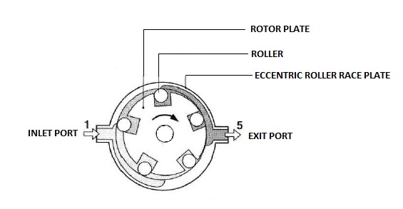
The electric pump is a roller cell pump which delivers fuel from the tank to the fuel rail at a pressure of approximately 5 bar. The roller cell pump is driven by a permanent magnet electric motor.

It consists of a roller race plate which is eccentric in shape. A rotor plate with notches (4 to 6) around its circumference is placed eccentrically inside the roller race plate. Each notch is provided with a roller. The roller race plate has an inlet port and an exit port.


When the engine is switched ON, the electric motor drives the pump. The motor drives the rotor plate inside the roller race plate. Due to the eccentric shape of the race plate, the rollers in the rotor move outwards pressing against the roller race plate due to centrifugal force. The fuel is trapped between the roller and the notch in the inlet port side and as the rotor rotates towards the exit port side, the fuel is pressurized and sent out through the exit port.


A check valve before the pump ensures that the fuel doesn’t flow back to the tank.


Fuel Accumulator:

Fuel accumulator is provided to maintain the pressure in the fuel system for a certain amount of time after the engine is switched OFF. This is done in order to help in easy restarting of the engine, especially when the engine is hot.


The accumulator is divided into 2 chambers with the help of a diaphragm. One chamber acts as the fuel accumulator and the other chamber is connected to the atmosphere. When the engine is running, the fuel enters the accumulator volume and pushes the diaphragm against the spring force. The diaphragm moves until the springs halt in the spring chamber. Thus the fuel collected at this point is the maximum accumulator volume.

Fuel Filter:


Fuel filter is often a combination of a paper filter, followed by strainer. This ensures higher degree of filtration. The paper filter has an average pore size of 10 µm.

Pressure Regulator:

A pressure regulator is fitted to one end of the fuel distributor. It is used to maintain the pressure in the fuel system constant at about 5 bar. It consists of a plunger which slides in the regulator against a spring. When the fuel supplied by the fuel pump exceeds the limit, the plunger moves against the spring to open the exit port. This allows the excess fuel to return to the fuel tank and thus maintaining the pressure.


When the fuel delivery quantity is lower, the plunger shifts back closing the exit port to allow less fuel to escape to the tank. The constant shifting of the plunger maintains the pressure in the rail.

Fuel Injection Valve:


Fuel injection valve open at a given pressure and atomize the fuel and inject onto the intake valves. They have a valve needle which sit on a valve seat. When the pressure is high enough, for e.g. more than 3.5 bar, the valve needle is raised from the valve seat, thus allowing the fuel to escape. The valve needle oscillates at a high frequency when operated. This results in excellent atomization of the fuel even if it is of small quantity.

AIR-FLOW SENSOR:

The air flow sensor here works on suspended body principle. As we are aware that the air flow quantity will decide the fuel injection quantity, accurate measurements of the air flow is required. The air flow sensor is located upstream of the throttle valve. It consists of an air funnel over which a sensor plate is free to pivot.


The air flowing through the air funnel deflects the sensor plate from its zero position to a certain amount. This movement of the sensor plate is transmitted to a control plunger of the fuel distributor via a lever. The movement of the control plunger decides the quantity of fuel to be injected.

FUEL DISTRIBUTOR:


Depending on the position of the sensor plate in air flow sensor, the fuel distributor meters the sufficient quantity of fuel to be distributed to individual cylinders. The movement of the sensor plate is transmitted to a control plunger of the fuel distributor via a lever. The control plunger moves in a barrel. The barrel is provided with metering slits.


Based on the position of the control plunger in the barrel, the control plunger opens or closes the metering slits to a larger or smaller extent. For instance, if the air flow rate is high, then the control plunger will move a larger distance against the spring to open the metering slit to a greater extent. As a result, more fuel will be delivered to the injection valve.  

Related Topics:

Gasoline:
Diesel:

Wednesday, 13 April 2016

Common Rail Direct Injection (CRDI)- Diesel

Today’s diesel engines are cleaner, more economical and more fuel efficient than ever before. Common Rail Direct Injection (CRDI) is the most advanced technology in diesel fuel injection. The name implies that the injection takes place directly inside the combustion chamber.

Difference between CRDI and an ordinary diesel injection system:

The difference between an ordinary diesel injection system and CRDI is that in an ordinary system, the fuel has to be pressurized for each injection cycle. In the case of CRDI, a common rail is installed which maintains the pressure of the fuel throughout its entire length. The Electronic Control Unit (ECU) regulates the fuel pressure at different speeds and also modulates the fuel supply required based on the operating conditions. Therefore, with the help of an ECU, fuel compression and injection are made independent of each other. This feature helps in lowering emissions and increasing fuel economy.

History of CRDI:

Robert Huber of Switzerland developed the first prototype of CRDI in 1960. Denso Corporation of Japan developed the common rail system for heavy duty vehicles and it was successfully installed in Hino Rising truck in 1995.

The modern CRDI which is controlled extensively by ECU have electrically controlled injectors replacing the mechanical ones. This system was prototyped in 1990s by Fiat, Magneti Marelli and Elasis. But the German company Bosch GmbH acquired the design for completion and mass production. Bosch ultimately bought the license from Fiat. The first passenger car to have a CRDI was Alfa Romeo 156 2.4 JTD in 1997.

Working of CRDI:

The common rail system is equipped with a high pressure pump which can pressurize the fuel up to 2000 bar. The pressurized fuel is then sent to a common rail which maintains the pressure throughout its entire length. The common rail is fitted with a rail pressure sensor to detect the pressure inside the rail. A pressure limiter valve is also provided in common rail. Controlled via the ECU, the pressure limiter valve limits the pressure in the rail, while at the same time suppressing pressure fluctuations.


In a CRDI, the fuel quantity and timing of injection is governed by the ECU or microprocessor. The common rail supplies fuel to each injector based on the firing order of the engine. The piezoelectric injectors are controlled by the ECU.

To lower the engine noise and vibration, the injector can be controlled to inject a small amount of fuel just before the main injection. This is known as ‘pilot’ injection. The pilot injection is followed by main injection. Some advanced CRDI injectors can achieve multiple injections (5 to 10) during main injection. This helps in lowering noise and emissions. The main injection is usually followed by a post injection.

The start of injection occurs at a pre-determined pressure and also ends at the same pre-determined pressure. Therefore, the pressure is maintained throughout the injection process, thus forming a square injection rate.


Related Topics:

Thursday, 24 March 2016

L-Jetronic Fuel Injection System

The L-Jetronic is an electronically controlled fuel injection system which has the advantage of direct air flow sensing. It injects intermittently into the intake ports. The task of a fuel injection system is to supply precise amount of fuel to the combustion chamber at that particular moment.

An engine’s operating conditions keep changing rapidly, hence fuel injection system should be fast enough to adhere to the changes and vary the fuel supply quantity at that very moment. L-Jetronic, which is an electronically controlled fuel injection system, is particularly suitable for the above mentioned conditions.


The control unit processes signals from a variety of sensors and calculates the exact amount of fuel to be supplied to the combustion chamber.

Functions of L-Jetronic:
There are 3 major functions of an L-Jetronic:

·         To pressurize fuel: L-jetronic system supplies fuel from tank to the intake valves at a certain pressure required for injection. Maintaining the pressure throughout the supply is at most important.

·         To monitor the sensors: The control unit has to register the important signals from various sensors such as air-flow sensor, throttle valve sensor, engine speed sensor, engine temperature sensor, etc.

·         To regulate fuel quantity: The signals from the sensors are processed by the control unit and pulses are generated to vary fuel injection amount.

DESIGN OF L-JETRONIC’S FUEL SYSTEM:
The fuel system of an L-Jetronic consists of the following components:
  •   Electric pump
  •    Fuel Filter
  •    Fuel rail
  •   Pressure regulator
  •    Fuel injectors

Electric Pump:
The electric pump is a roller cell pump which delivers fuel from the tank to the fuel rail at a pressure of approximately 2.5 bar. The roller cell pump is driven by a permanent magnet electric motor.


It consists of a roller race plate which is eccentric in shape. A rotor plate with notches (4 to 6) around its circumference is placed eccentrically inside the roller race plate. Each notch is provided with a roller. The roller race plate has an inlet port and an exit port.

When the engine is switched ON, the electric motor drives the pump. The motor drives the rotor plate inside the roller race plate. Due to the eccentric shape of the race plate, the rollers in the rotor move outwards pressing against the roller race plate due to centrifugal force. The fuel is trapped between the roller and the notch in the inlet port side and as the rotor rotates towards the exit port side, the fuel is pressurized and sent out through the exit port.

A check valve before the pump ensures that the fuel doesn’t flow back to the tank.

Fuel Filter:

Fuel filter is often a combination of a paper filter, followed by strainer. This ensures higher degree of filtration. The paper filter has an average pore size of 10 µm.

Fuel Rail:

The function of a fuel rail is to maintain the pressure and to supply equal amount of fuel to each injector.

Pressure Regulator:

Pressure regulator is provided at one end of the fuel rail. It maintains the pressure difference between the fuel rail pressure and the manifold air pressure. The injection of fuel by the electronic fuel injectors depends on the inlet valve opening time. Therefore, the pressure in the fuel rail depends directly on the inlet manifold pressure.


The pressure regulator is a diaphragm controlled regulator which regulates fuel pressure at 2.5 bar. If the pressure exceeds the set pressure, then the fuel from the rail flows back to the tank via a return valve in the regulator. The diaphragm is pre-loaded by a spring and the diaphragm chamber is connected to the inlet manifold stream through a tube. Another chamber is provided for the fuel return valve and line. The fuel flows back to the tank without any pressure.

Electronic Fuel Injectors:

The electronic fuel injectors inject precise amount of fuel over the inlet valves. Each cylinder is provided with its own fuel injector. All the injectors are solenoid operated valve. The solenoid is controlled by electric pulses which are generated by the control unit (ECU).


The solenoid valve is provided with a solenoid winding. There is a needle valve sitting inside the winding. The needle is pressed against its seat with the help of a helical spring. When electric pulse is passed, the solenoid winding is magnetized and the needle valve lifts from its seat to allow the fuel to be injected through the orifice. The front end of the needle is pintle shaped for better atomization of the fuel. The needle is lifted approximately 0.08 to 0.1 mm from its seat.

SENSORS:

Sensors are an essential part of the L-Jetronic system as it detects the operating conditions of an engine. The most important ones are the engine speed sensor and the air-flow sensor.

Air-flow sensor:

Air-flow sensor measures the force of air on the air-flow sensor flap. The sensor flap moves against the opposing spring forces. The flap moves in proportion to the air flow and the compensation flap also moves the same distance as the sensor flap moves. The compensation flap is connected to a variable resistance potentiometer.


When the flap moves, a voltage is generated in proportion to the distance it moves. The closed position of the flap will generate zero voltage and fully open position will generate approximately 5 V. There is an idling air passage to allow some amount of air to flow when the engine is running at idling speed.


Wednesday, 16 March 2016

Distributor Fuel Injection Pump

Fuel injection pumps play an important role in delivering fuel to the injectors at the required pressure and timing. The injection sequence should be faster, which requires the pump to be compact and light in weight. Distributor type fuel injection pump fits the criteria of light weight and compact design. It also goes by the name axial-piston distributor pump.

In the year 1962, Bosch introduced its first distributor type fuel injection pump and since then it has been widely used in almost all types of vehicles. It houses a compact governor and all together the pump’s size is pretty much smaller than the inline fuel injection pumps. The pump and governor has been continuously improved over a period of time to meet the low fuel consumption and low emission demands.


For an in-direct fuel injection, a distributor pump generates 350 bar of pressure. Whereas, for a direct fuel injection system, it generates pressure in a range of 900 bar to 1900 bar. The pressure generation depends on the speed of the engine. They can be used in engines having 3 to 6 cylinders.
There are two types of distributor pumps:

·         VE type pump: These are also known as axial piston distributor type pumps. The piston compresses the fuel by moving in an axial direction relative to the drive shaft.

·         VR type pump: It is also known as radial piston type distributor pump. These have multiple pistons arranged in a radial direction relative to the drive shaft motion. The pressure achieved in VR pumps is higher than that of VE pumps.

This article will concentrate on VE pumps alone. It relies on a single piston to distribute fuel to all the cylinders of an engine.

FUEL SYSTEM LAYOUT:


The fuel injection system consists of a fuel tank. Fuel from the tank is supplied to the VE type distributor fuel injection pump via a fuel filter. The fuel is supplied with the help of a pre-supply pump if the tank is located at a lower position compared to the fuel injection pump. Fuel is pressurized in the fuel injection pump and then delivered to the nozzles. In addition, there is a solenoid shut off valve to block the flow of fuel to the high pressure fuel injection pump when the ignition is switched OFF. The fuel flow is varied with the help of a mechanical governor.  A hydraulic timing device is used to vary the fuel injection timing.

FUEL SUPPLY STAGE:
In the fuel supply stage, fuel is supplied from the tank to the fuel injection pump at the required pressure. This stage comprises of the following components:
  •          Fuel tank
  •          Pre-supply pump in fuel tank (optional)
  •          Fuel filter
  •          Fuel lines (Low pressure)
  •          Vane pump (Low pressure pump which is integrated in the high pressure pump)
  •          Pressure Control Valve (PCV)

Fuel Tank:
It should be corrosion resistant and should prevent leaking of fuel even if the pressure goes beyond the operating pressure of at least 0.3 bar.

Fuel Lines:
The fuel lines are made of flame resistant metal tubing. It should be strong enough to prevent damage and should avoid leakage that can occur at twists and turns.

Fuel Filter:
It reduces the level of contamination by removing solid particles. To ensure that the solid particles not clog the filter, a separate storage is provided for the removed particles.

Vane type pump (Low pressure pump):

It sucks the fuel from the tank and supplies it to the high pressure distributor pump. For each rotation, it supplies a constant amount of fuel to the high pressure pump. As the speed increases, the amount of fuel supplied also increases.

Vane pump’s impeller is mounted on the inside of the drive shaft through a key and keyway arrangement. The drive shaft runs the impeller. Impeller is surrounded by an eccentric ring which is mounted in the pump housing. An impeller has 4 floating blades which float outwards against the eccentric ring.


As the drive shaft rotates the impeller, the floating blades are pressed outside against the eccentric ring as a result of centrifugal force. Fuel from the tank flows through the inlet passage provided in the housing and is collected in the chamber formed by the impeller, any 2 floating blades and eccentric ring. As the shaft keeps rotating, the fuel in the chamber is transferred to a constricted space. As a result of this, fuel is pressurized to a margin of 4 bar at idling speed and 10 bar at maximum speed of engine. The low pressure fuel then escapes out through the spill port.


Due to the shape of eccentric ring, the volume of the chamber in which the fuel is collected is reduced when it rotates to the fuel discharge side. This arrangement pressurizes the fuel.
Both the fuel inlet side and fuel discharge side has kidney shaped cells. The inlet side has the fuel inlet bore connected to the fuel inlet passage and the discharge side has the spill port which supplies fuel to the high pressure pump.


Pressure Control Valve (PCV):

As the speed of the drive shaft increases, the pressure generated by the vane pump also increases. This pressure governs the functioning of the hydraulic timing device. Therefore it is important that the pressure generated should not exceed the optimum pressure.


A pressure control valve is used to control the internal pressure. It consists of a spring loaded valve. When the internal pressure is beyond a set value, then the valve plunger is pushed against the force of the compression spring. As a result, the return line is exposed and the fuel escapes through the return line. This reduces the internal pressure. The return line is placed adjacent to the fuel discharge side of the vane pump.

The fuel that escaped through the return line is directed back to the fuel inlet side of the vane pump through an internal passage. The opening pressure of the spring loaded valve can be adjusted by varying the spring tension.

DISTRIBUTOR PUMP DESIGN:

The distributor pump has a compact body in which various parts are integrated together. A typical distributor pump is made of the following components:

  •    Vane pump (Low pressure pump)
  •     High pressure distributor pump
  •      Mechanical governor
  •      Hydraulic timing device
  •      Solenoid shut off valve

HIGH PRESSURE DISTRIBUTOR PUMP:

The high pressure pump has one plunger or piston that pressurizes the fuel and then distributes it to individual cylinders through high pressure fuel lines and nozzles. The fuel is delivered at the specified timing and quantity. The distributor pump consists of the following components:

·         Distributor Plunger/Piston:
The rotational motion from the drive shaft is transferred to the plunger via a roller ring assembly, cam plate and yoke assembly. So the entire unit rotates at the same speed. The cam plate provides the reciprocating motion to the plunger. A plunger has vertical grooves equal to the number of cylinders in an engine. The vertical grooves act as fuel inlet passage to the barrel during inlet stroke of the piston. The stroke movement of plunger is 2.2 to 3.5 mm depending on the type of pump.


The plunger moves to Top Dead Centre (TDC) and compresses the fuel. Two symmetrically arranged plunger return springs push the plunger back to Bottom Dead Centre (BDC) after fuel compression has taken place. The plunger has a fuel delivery line running through its length and this line is connected to the distributor port and spill ports.


·         Cam Plate:


Cam plate has cam profiles which help in plunger reciprocation. The number of cam profiles is equal to the number of cylinders in an engine. The design of cam profiles affects the injection pressure and the injection duration.

·         Distributor Body:


The plunger and barrel are precisely fitted into the distributor body. The plunger also has a control collar which covers and uncovers the spill port to vary fuel quantity. The barrel has distributor slots in its inner circumference which supply fuel to the respective injectors via delivery valve. The distributor body also has a electric shut off valve to block the supply of fuel to the barrel when engine is switched OFF.


FUEL METERING INSIDE THE DISTRIBUTOR BODY:
The distributor body generates the pressure required for fuel injection. There are several phases of plunger stroke for precise fuel metering to take place.

·         Intake stroke:

When the piston moves from top dead centre (TDC) to bottom dead centre (BDC), one of the vertical grooves match with the fuel inlet passage and thus the fuel enters the plunger barrel.

·         Pre-stroke:

As the plunger keeps rotating, it closes the inlet passage. Now the piston starts moving from BDC to TDC and some amount of fuel flows back to the inner chamber of the pump through a slot provided at the top of plunger (also known as pre-stroke groove). Pre-stroke is necessary to prevent slow rise in injection pressure.

·         Effective stroke:

As the plunger moves further up towards TDC, the pre-stroke groove is closed and the injection pressure increases rapidly due to compression. The fuel is delivered to the delivery slot and then supplied to the delivery valve. The delivery valve lifts from its seat and allows the fuel to escape to the injector.

·         Residual stroke:

The effective stroke is complete when the spill port at the bottom of the plunger is exposed. This allows the fuel to escape to the pump’s internal chamber and thus the pressure inside the barrel is releases and there is no more fuel delivery to the injector.

VARIABLE SPEED GOVERNORS:
Variable speed governors are used to control the engine speeds from start to intermediate speed range and also controls it at high speeds. Speed variation is achieved by varying the fuel quantity.

Design:

The design is pretty much different compared to the one in Inline Fuel injection pumps. It consists of a flyweight housing with 4 flyweights. The flyweight housing has a gear at the bottom which is meshed with the drive shaft. It is mounted in its position with the help of a governor shaft. As the flyweights rotate, the movement is transferred to the sliding sleeve which slides up against the starting lever of the governor.


The governor mechanism consists of a starting lever, control lever and tensioning lever. At the end of the starting lever is a ball pin which engages with the control collar of the distributor plunger. A starting spring is attached to the top of the starting lever. There is an idle speed spring attached to the retaining stud at the top of the tensioning lever. A governor spring is attached to the retaining stud on one end, whereas the other end is connected to the rotational speed control lever via a linkage. The rotational speed control lever is linked to the accelerator pedal.


The governor spring tension and the flyweight force transfer the movement to the ball pin. The movement of the ball pin moves the control collar to vary the quantity of fuel delivered to the injectors.

The fuel quantity varies at different speeds. This is done with the help of a variable speed governor.

·         Starting speed:


When the engine is not running, the distributor pump doesn’t supply the fuel to the injectors and the flyweights and sliding sleeve of the governor rests at base position. At this point, the starting spring pushes the starting lever into its position and the movement is transferred to control collar which is brought to starting position. The effective stroke of plunger during position is higher. This allows maximum fuel to be delivered to the engine for starting. For starting the engine, the rotational speed control lever is pressed against the maximum speed screw.

·         Idle speed:

The starting lever force is overcome by a slight increase in engine speed. As the speed starts increasing, the flyweights’ radial movement results in the axial movement of the sliding sleeve which presses the starting lever against the force of starting spring. This results in the movement of control collar bringing it to idle speed position. The effective stroke is minimum for idling speed and this results in lesser fuel delivery to the injectors. The accelerator pedal is released and the rotational speed control lever rests against the idling speed screw.

The idle speed spring mounted in the retaining stud maintains a state of equilibrium with the flyweights’ force and maintains the starting lever in its position. This allows a steady amount of fuel to be delivered to the injector.

·         Operation under load:

When the accelerator pedal is pressed, the rotational speed control lever assumes a position between idle speed screw and maximum speed screw. When the speed of the engine goes beyond the idling speed, the starting spring and the idling speed spring are fully compressed and have no control over the movement fuel flow in this range.

The governor spring has the control over this speed range. When the accelerator pedal is pressed, the rotational speed control lever moves from its idle speed position to a position corresponding to the speed. This compresses the governor spring and the governor spring force exceeds the flyweights’ centrifugal force. As a result, the starting lever rotates and transfers the movement to the control collar. The effective stroke is increased and more fuel is delivered to the engine, thereby increasing the speed.

When the accelerator pedal is fully pressed (Wide open throttle), more amount of fuel is delivered as a result of governor spring’s control over the starting lever. As the speed increases, the flyweights’ centrifugal force increases and the sliding sleeve moves to oppose the spring force. The control collar remains in its wide open throttle position until the opposing forces between flyweights and governor spring achieve equilibrium.

If the speed of the engine further increases, the flyweights’ centrifugal force overcomes the governor spring force and reduces the effective stroke of plunger, thereby leading to speed reduction. Further increase of speed will lead to fuel being cut off

·         Engine Overrunning:
One of the features of a variable speed governor is to prevent overrunning of engines while descending a slope or a hill. The engine is driven by vehicle’s inertia. At this point the sliding sleeve presses against the starting lever and tensioning lever. The starting lever rotates in its axis to transfer the movement to control collar, wherein the collar brings the effective stroke to minimum or zero (in case engine is switched OFF).