Wednesday 30 March 2016

Sliding Mesh Gearbox

Sliding mesh gearbox is the simplest type of gearbox. It looks similar to a constant mesh gear box, except that the main shaft gears are not always in contact with the counter shaft gears.

The individual gear ratio is obtained by sliding the selected gear wheel axially. The gear wheels are splined in the main shaft and can be slid to obtain different gear ratios.

One major problem with sliding mesh is the absence of synchronizer units as found in the constant mesh. While changing the gear ratio, the speeds have to be matched before engagement of the gears. Due to the unavailability of synchronizer teeth, the gears might collide with each other and generate a lot of noise. This can even damage the gears.

The gears are provided with spur straight teeth, in order to avoid any side thrust while engagement. This type of gearbox is used in very few vehicles where compact assembly is required. The shaft and gears are made of low alloy nickel-chromium-molybdenum steel.  

Design:

The input shaft from the engine drives the counter shaft. Both input and counter shaft gears are in constant mesh with each other. All the other gears on the counter shaft are rigidly fixed and rotate with the shaft. The main shaft or the output shaft is held in the same axis as that of the input shaft.


The main shaft gears are not in constant mesh with the counter shaft gears. The gear wheels on the main shaft can be slid axially to achieve different gear ratios. The different gear ratios are obtained as following:

Neutral Gear:

In this case, none of the main shaft gears are meshed with the counter shaft gears. Hence, the drive from the input shaft is not transferred to the main shaft. The wheels remain stationary.

1st Gear:

In 1st gear, the gears D and F are meshed to form a lower gear ratio. Since the gear F is bigger (30 teeth) and has more number of teeth than the gear D (10 teeth), the main shaft rotates at a lower speed. The torque is highest and speed is lowest at 1st gear. This is to facilitate easy movement of the car from standstill.
If the counter shaft is rotating at 1000 rpm (N1), then the main shaft speed (N2) can be calculated as
N1/N2 = TF/TD
N2 = N1 X (TD / TF)
N2 = 1000 X (10/30)
N2 = 333.33 rpm
Where,  N1 = speed of counter shaft
              N2= speed of main shaft
              TD = number of teeth in gear D
              TF = number of teeth in gear F

2nd Gear:

In 2nd gear, the gear E is slid and meshed with gear C. The number of teeth in gear E (TE) is reduced, or example TE = 22. The number of teeth in gear C is increased (TC= 15). This increases the speed of the car and the torque is reduced.

If the counter shaft speed (N1 = 1000 rpm), then the main shaft speed (N2) is

N2 = N1 X (Tc / Te)
N2 = 1000 X (15/22)
N2 = 681.81 rpm


3rd gear or Top gear:

In 3rd gear, the main shaft is slid axially to mesh with the input shaft. In this case, the drive from the input shaft is directly transferred to the main shaft. The input shaft has a gear with internal teeth that mesh with the main shaft gear with external teeth. The vehicle can achieve top speed in top gear and the torque is lowest at this point.

Reverse Gear:

In reverse gear mechanism, an idle gear ‘I’ is used in between the gears G and F. The gears G and F are not in direct contact. The idle gear I is driven by G and the gear I drives the gear F. In this way, the direction of rotation of the main shaft is reversed and hence the vehicle moves backward.


Vehicle Insurance to get costlier

Vehicle insurance is all set to get costlier from April 1, 2016. The Union budget presented in the parliament has prompted the hike in insurance rates of different vehicles. Insurance Regulatory and Development Authority (IRDA) has confirmed a hike of up to 40 % in third party motor insurance premium rates for the year 2016-2017.

The hike for vehicles falling under different category is as follows:


Vehicle Category
Percentage hike
Cars under 1500 cc
40 %
Cars above 1500 cc
25 %
Motorcycles under 75 cc
9.6 %
Motorcycles between 75 cc and 150 cc
15 %
Motorcycles between 150 cc and 350 cc
25 %
Motorcycles beyond 350 cc
-10 %
Auto rickshaws
3.2 %
Public Carriers
15 to 30 %
Goods vehicles or trucks (below 12,000 kgs)
0 %

How manual transmission works

Engine crankshaft rotates at a high speed. The high speed power cannot be directly transmitted to the wheels, as it would start rotating at an uncontrollable speed and the driver won’t have any control over the speed on different driving conditions. Therefore, speed reduction is necessary between engine and the wheels. Manual transmission uses a set of gears that help in speed reduction.

The manual gearbox provides a set of gears with different sizes and different number of teeth for different driving conditions. The wheels will be slowest at the 1st gear and fastest at the top gear. Manual transmission is the most popular form of transmission.

In this article, we will learn about the working of a 4 speed manual gear box with reverse gear.

Why is a transmission necessary?

A vehicle requires moving at different speeds on different conditions. For example, a vehicle moving on a slope requires more torque and hence the vehicle should be operated at lower gear (1st gear). The higher the torque, the lower is the power from the engine. Whereas, a vehicle moving on a straight surface with less traffic can be operated at higher speeds by switching to higher gears (4th gear).

Principle of manual transmission:

Manual transmission works on a simple principle of gear ratios. A basic gearbox consists of an input shaft from the engine, an output shaft or main shaft that delivers power to the differential and a counter shaft that transmits the power from input to output shaft.

The power from the input shaft drives the counter shaft and the counter shaft in turn drives he output shaft of main shaft.

Constant Mesh Gearbox:

This is the most common type of manual gearbox used in a vehicle. It consists of an input shaft, a lay shaft or counter shaft, a main shaft or output shaft and a synchromesh device.

The engine drives the input shaft, which in turn drives the counter shaft. The counter shaft gears and the main shaft gears are in constant mesh with each other all the times. That’s why it is called constant mesh gearbox.


The counter shaft gears drive the main shaft gears. But the main shaft gears rotate freely over the bearings and don’t rotate the main shaft unless one of the main shaft gears is locked with the main shaft using the synchromesh device.

The synchromesh device is splined to the main shaft and can slide from left to right or vice-versa. The synchromesh device is commonly known as dog clutch and is operated by means of a selector rod.

Hub and Sleeve arrangement:

There is a hub which is splined to the main shaft and rotates along with the shaft. The hub has external teeth over which a sleeve with internal teeth can slide as per the gear ratio required. Each gear on the main shaft is provided with a synchronizer cone teeth arrangement which rotates freely over a bearing. If the sleeve meshes with the teeth of the synchronizer cone, it is clear that both gear and main shaft will be locked and will start rotating at the same speed.

Synchronizer Ring:

But during the gearbox operation, both the main shaft and main shaft gears will be rotating at different speeds. Hence, meshing the sleeve with the synchronizer cone is a difficult task and can generate a lot of noise. To overcome the problem, a synchronizer ring is provided between the sleeve and the synchronizer gear to match the speed of the gear with the shaft before being meshed with each other.

The synchronizer ring not just rotates along with the hub, but also slides axially.

Engagement of sleeve and synchronizer cone teeth:

When clutch pedal is pressed, the power flow from the engine to transmission is blocked. The sleeve is slid towards the required gear with the help of a selector rod. The sleeve pushes the synchronizer ring against the synchronizer cone.

Due to high frictional force between the cone and the ring, the speed of the gear is matched with the speed of the shaft. When the speeds match, the sleeve is slid further towards the cone and meshes with its teeth. Hence, both gear and the main shaft are locked and both start rotating at the same speed.

The same principle is followed to shift to other gears.

Different gear ratios:

Neutral gear:

All the gears on the main shaft are in constant mesh with the gears on the counter shaft. The gears on the main shaft rotate freely and none of the gears are synchromeshed with the main shaft. Hence, no drive is transmitted from the input shaft to the output shaft.

1st gear:

The smallest gear (lowest number of teeth) in the counter shaft is synchromeshed with the largest gear (highest number of teeth) on the main shaft. Thus we can achieve maximum torque and minimum speed. 1st gear is ideal for a standing start of the engine.

2nd gear:

In 2nd gear, the gear in the middle of the counter shaft is synchromeshed with the 2nd biggest gear on the main shaft. This increases the speed and reduces the torque to a certain level. 2nd gear ratio is ideal for cars ascending a hill.

3rd gear:

The biggest gear on the counter shaft is synchromeshed with the smallest gear on the main shaft to increase the speed further and reduce the torque. This gear ratio is ideal for cruising.

4th gear:

The input shaft gear is directly synchromeshed with the main shaft to provide a direct drive from the input shaft to the main shaft. The vehicle can reach its top speed at top gear.

Reverse gear:

The reverse gear uses an idle gear to be meshed between an input gear on the counter shaft and an output gear on the main shaft. When the driver selects the reverse gear, the idle gear is slid in between the two gears. This reverses the direction of rotation of the main shaft.

There is no synchronizer cone and ring mechanism for reverse gear. Hence, reverse gear can only be used when the transmission operation is stopped completely and none of the shafts are rotating. The gear ratio is kept low for reverse, since a vehicle requires more torque when it is moving from a standstill.


Related Links:


Tuesday 29 March 2016

Tata Tiago launch date and features

Tata’s brand new hatchback Tiago is all set to release on April 6th, 2016 in India. The car will look to gain more popularity which its previous models such as Vista and Bolt couldn’t. Tiago is expected to be launched with a starting price of INR 3.80 lakhs and will give direct competition to Hyundai i10 and Maruti Celerio.


Here are some of the features that we can expect with the launch of Tiago:
·         1.2 liter petrol engine Revotron XZ would generate 84 bhp and a torque of 114 Nm.
·         1.05 liter diesel engine Revotorq XZ would generate 69 bhp and a torque of 140 Nm.
·         Petrol engine would give a mileage around 21 kmpl.
·         Diesel engine would give a mileage around 25.8 kmpl.
·         Both petrol and diesel variants will only have manual transmission. No automatic on offer.
·         Integrated music system, electric mirror and chilled glovebox.
·         Harman’s 8 speaker sound system, which is the best in this class.
·         2 dedicated smartphone apps developed especially for Tiago users- turn by turn navigation app and juke car app.
·         Driver can switch between ECO mode and CITY mode to vary engine performance.
·         A boot space of 240 liters.
·         Dual front air-bags.

·         ABS and EBD system installed

Sunday 27 March 2016

Exhaust Gas Recirculation (EGR)

Exhaust Gas Recirculation (EGR) is an emission control system used to reduce NOX emissions in particular. It redirects some amount of exhaust back to the combustion chamber of an engine to dilute the oxygen in the intake stroke and reduce the combustion temperature.

NOX is produced at peak engine temperature and the emission is higher when the oxygen content in the intake is high (lean mixture). At high temperatures, nitrogen combines with oxygen to form various oxides of nitrogen (collectively known as NOX). NOX is responsible for the formation of smog in cities.

Design and Operation of EGR:

The exhaust from the engine is re-circulated only when a vacuum operated valve opens. The EGR valve is operated by the exhaust back pressure. At a particular back pressure range, EGR valve allows some amount of exhaust to be sent back to the combustion chamber.

The exhaust gas is an inert gas, hence it cannot be burned. It dilutes the fresh air in the inlet manifold, thus reducing the oxygen content. The inert gases also absorb the combustion chamber heat to reduce the peak temperature.


 The exhaust gases pass through an EGR cooler to reduce its temperature. Reducing the temperature of exhaust helps in reducing the peak temperature of the cylinder.

In an S.I. engine, EGR re-circulates 5 % to 15 % of the exhaust. Excess amount of recirculation can compromise engine efficiency. EGR is not used at engine idling speed to avoid unstable combustion. It is also not used at high loads as we require high power output to gain high speeds and EGR would just prevent high oxygen intake at high loads.

In a diesel engine, exhaust can be re-circulated as high as 50 % as diesel engine is not subjected to continuous flame front and knocking.

In the mid-1990s, pneumatic EGR valves became more popular in EGR system. It consists of an electromagnetic valve which is operated by vacuum. Vacuum is usually generated by the pressure difference between inlet manifold and exhaust manifold.


Fuel Vapor Canister

Canister is a pollution control device used mainly in gasoline fuel tanks to prevent the vapors of the fuel escape from the tank. Gasoline gets easily vaporized, and evaporated gasoline can increase the emissions because it is a mixture of hydrocarbons (HC) which is harmful for both environment and humans. This system is also known as Evaporative Emission Control System (EVAP) or fuel vapor canister or carbon canister.

Fuel vapor canisters were first used in the mid-1970s and it significantly reduced the HC emissions. Gases escaping from the tank or engine result in HC emissions.

To prevent the evaporated fuel to escape unburned, fuel vapor canister is used to trap all the vapors and then store and use it later when the engine is switched ON. A fuel vapor canister only works when the engine is OFF.

Design of Canister:

There is an inlet port and an outlet port. The canister is filled with charcoal. The charcoal traps the gas and then sends it out via the outlet port. When the gasoline vaporizes, the vapors from the tank escape through a vent line and then reach the canister through the inlet port. The outlet port is connected to a purge valve which prevents the fuel from entering the inlet manifold unless the engine is switched ON.


A carburetor vent line is provided for the fuel bowl in the carburetor. The fuel in the carburetor bowl will vaporize when the temperature rises. The vaporized fuel is supplied to the canister through the carburetor vent line.

The canister is provided with a purge air line at the bottom which allows the air from the atmosphere to enter the canister and form a fuel-air mixture.

Working of a Fuel Vapor Canister:


The evaporated gases reach the canister through the vent port and reach the carbon canister. The gases are trapped inside due to its properties to trap hydrocarbons. The gases are stored in the canister. When the engine is switched ON, suction is created in the intake manifold which prompts the purge valve to open and this allows the air to be sucked inside the canister through an air filter. The air from the purge air line pushes the gasoline vapors from the canister to the intake manifold. The air-fuel mixture is then supplied and burned inside the combustion chamber. The canister stops working when the engine is switched ON. Fuel vapor canister can only be used in a vehicle having a carburetor. 

Thursday 24 March 2016

L-Jetronic Fuel Injection System

The L-Jetronic is an electronically controlled fuel injection system which has the advantage of direct air flow sensing. It injects intermittently into the intake ports. The task of a fuel injection system is to supply precise amount of fuel to the combustion chamber at that particular moment.

An engine’s operating conditions keep changing rapidly, hence fuel injection system should be fast enough to adhere to the changes and vary the fuel supply quantity at that very moment. L-Jetronic, which is an electronically controlled fuel injection system, is particularly suitable for the above mentioned conditions.


The control unit processes signals from a variety of sensors and calculates the exact amount of fuel to be supplied to the combustion chamber.

Functions of L-Jetronic:
There are 3 major functions of an L-Jetronic:

·         To pressurize fuel: L-jetronic system supplies fuel from tank to the intake valves at a certain pressure required for injection. Maintaining the pressure throughout the supply is at most important.

·         To monitor the sensors: The control unit has to register the important signals from various sensors such as air-flow sensor, throttle valve sensor, engine speed sensor, engine temperature sensor, etc.

·         To regulate fuel quantity: The signals from the sensors are processed by the control unit and pulses are generated to vary fuel injection amount.

DESIGN OF L-JETRONIC’S FUEL SYSTEM:
The fuel system of an L-Jetronic consists of the following components:
  •   Electric pump
  •    Fuel Filter
  •    Fuel rail
  •   Pressure regulator
  •    Fuel injectors

Electric Pump:
The electric pump is a roller cell pump which delivers fuel from the tank to the fuel rail at a pressure of approximately 2.5 bar. The roller cell pump is driven by a permanent magnet electric motor.


It consists of a roller race plate which is eccentric in shape. A rotor plate with notches (4 to 6) around its circumference is placed eccentrically inside the roller race plate. Each notch is provided with a roller. The roller race plate has an inlet port and an exit port.

When the engine is switched ON, the electric motor drives the pump. The motor drives the rotor plate inside the roller race plate. Due to the eccentric shape of the race plate, the rollers in the rotor move outwards pressing against the roller race plate due to centrifugal force. The fuel is trapped between the roller and the notch in the inlet port side and as the rotor rotates towards the exit port side, the fuel is pressurized and sent out through the exit port.

A check valve before the pump ensures that the fuel doesn’t flow back to the tank.

Fuel Filter:

Fuel filter is often a combination of a paper filter, followed by strainer. This ensures higher degree of filtration. The paper filter has an average pore size of 10 µm.

Fuel Rail:

The function of a fuel rail is to maintain the pressure and to supply equal amount of fuel to each injector.

Pressure Regulator:

Pressure regulator is provided at one end of the fuel rail. It maintains the pressure difference between the fuel rail pressure and the manifold air pressure. The injection of fuel by the electronic fuel injectors depends on the inlet valve opening time. Therefore, the pressure in the fuel rail depends directly on the inlet manifold pressure.


The pressure regulator is a diaphragm controlled regulator which regulates fuel pressure at 2.5 bar. If the pressure exceeds the set pressure, then the fuel from the rail flows back to the tank via a return valve in the regulator. The diaphragm is pre-loaded by a spring and the diaphragm chamber is connected to the inlet manifold stream through a tube. Another chamber is provided for the fuel return valve and line. The fuel flows back to the tank without any pressure.

Electronic Fuel Injectors:

The electronic fuel injectors inject precise amount of fuel over the inlet valves. Each cylinder is provided with its own fuel injector. All the injectors are solenoid operated valve. The solenoid is controlled by electric pulses which are generated by the control unit (ECU).


The solenoid valve is provided with a solenoid winding. There is a needle valve sitting inside the winding. The needle is pressed against its seat with the help of a helical spring. When electric pulse is passed, the solenoid winding is magnetized and the needle valve lifts from its seat to allow the fuel to be injected through the orifice. The front end of the needle is pintle shaped for better atomization of the fuel. The needle is lifted approximately 0.08 to 0.1 mm from its seat.

SENSORS:

Sensors are an essential part of the L-Jetronic system as it detects the operating conditions of an engine. The most important ones are the engine speed sensor and the air-flow sensor.

Air-flow sensor:

Air-flow sensor measures the force of air on the air-flow sensor flap. The sensor flap moves against the opposing spring forces. The flap moves in proportion to the air flow and the compensation flap also moves the same distance as the sensor flap moves. The compensation flap is connected to a variable resistance potentiometer.


When the flap moves, a voltage is generated in proportion to the distance it moves. The closed position of the flap will generate zero voltage and fully open position will generate approximately 5 V. There is an idling air passage to allow some amount of air to flow when the engine is running at idling speed.


Sunday 20 March 2016

Oxygen Sensor

Lambda sensors or oxygen sensors are used in the vehicle exhaust system to analyse the proportion of oxygen in the fuel-air mixture used in a car. They help in determining the quality of air-fuel mixture; whether it is lean or rich. It is a vital component in a modern car to regulate the harmful emission gases. The amount of emission from a vehicle can affect the life of catalytic converters.

Why is an Oxygen sensor necessary?

If an oxygen sensor, the ECU can no longer sense the sir-fuel ratio. As a result, the engine might perform poorly if it doesn’t get the right air-fuel mixture. Even the engine emissions would shoot up in this scenario.

When was Oxygen sensor introduced?

Oxygen sensors were introduced by Bosch in the late 1960s. Volvo 240 was the first mass produced automobile to be installed with oxygen sensors in 1976.

Where is Oxygen sensor used?

Lambda sensors are used widely in petrol powered cars, since air flow can be controlled in petrol engines. Over the years it has become an essential part of the engine management system and emission control system. It is located in the exhaust system, between the exhaust manifold and catalytic converter.

Without a Lambda sensor, the modern electronic fuel injection is not possible. Even though, it is located in the exhaust manifold, it indirectly measures the air-fuel ratio. It measures the oxygen content in the exhaust gases and indicates the air-fuel ratio.

Quality of air-fuel mixture:

The stoichiometric air-fuel ratio for a petrol engine is 14.7:1. Engine requires different ratios at different conditions.

Less amount of oxygen in the exhaust indicates that it is a rich mixture, which results in wastage of fuel and unburned fuel results in excess emission.

Higher proportion of oxygen in the exhaust indicates that is a lean mixture, which can be a problem at higher engine operating temperature. At high temperature, lean mixture can produce more nitrogen oxide (NOX) emissions and can lead to misfiring of the engine.   

DESIGN OF OXYGEN SENSORS:

Oxygen sensors calculate the difference between the oxygen content in the exhaust and the amount of atmospheric oxygen. Based on the difference, it generates a voltage and sends it to the ECU. The ECU senses the voltage signal and regulates the air-fuel ratio to the optimum level.


An oxygen sensor is made of a ceramic material plated with platinum porous electrode (both on the inside and outside of the ceramic body). The ceramic body is placed inside a housing to protect the sensing element from any mechanical damages.
The ceramic material is usually made of zirconium dioxide or Zirconia. The surface of zirconia is plated with platinum electrode. The end of the oxygen sensor is provided with cables to carry the voltage signal to the ECU.

The zirconia element is covered in a steel shell provided with a lot of openings or slots for the exhaust gases to enter the shell and flow through the zirconia element. The Zirconia element side is placed inside the exhaust system, whereas the other end with the cables is outside the exhaust system.

WORKING OF OXYGEN SENSORS:

The exhaust gas flows through the zirconia element. Meanwhile, the atmospheric air flows through the gaps between the cables at the other end. The outside air is made to flow through an internal passage towards the zirconia end.

The exhaust gas flows through the platinum electrode coated on the outside of the zriconia material. The atmospheric air flows towards the platinum electrode coated inside the zirconia element. Both the Platinum electrodes are linked to a cable each which carries the voltage output. The difference in the concentration of oxygen molecules in the exhaust and atmosphere creates a potential difference.

The oxygen ions are driven from a platinum electrode with higher concentration of oxygen to the platinum electrode with lower concentration of oxygen. For example, if the ambient air has more oxygen molecules than the exhaust gases, then the oxygen ions will flow from inner platinum electrode to the outer.

The movement of oxygen ions generates a potential difference between the two electrodes. Lean mixture Will generate a potential difference of as low as 0.1 V. A rich mixture will generate a potential difference of 0.9 V.

The voltage signal is supplied to the ECU. The ECU compares the signal strength to the standard values set by the manufacturer and regulates the air-fuel mixture to the optimal value.


Wednesday 16 March 2016

What happens when we add petrol in a diesel car or vice-versa?

This is a very common doubt among people of all ages. Firstly, we should understand the common differences between petrol and diesel.
·         Petrol has higher self-ignition temperature (246 °C), compared to diesel (210 °C)
·         Petrol engines use spark plugs to ignite the petrol, whereas diesel self ignites due to the temperature and pressure created during compression ratio.
·         Petrol is highly volatile compared to diesel.
·         If petrol is ignited in a cylinder having a compression ratio exceeding 11:1, knocking becomes a common phenomenon.
·         Diesel needs to be injected at a very high pressure (1000 bar to 2000 bar) so that it is atomized and readily burns when injected inside the combustion chamber. Petrol is injected or mixed with air at a very low pressure of 2 to 4 bar.

When petrol is added in a diesel engine:
The temperature and pressure created during compression stroke will be very high in diesel engines. This will result in self-ignition of petrol. It will lead to knocking creating loud thumping noises. It will put a lot of stress on piston and cylinder walls leading to damage.

When diesel is added in a petrol engine:
The engine won’t start simply because diesel is less volatile and will not mix with air to form a combustible mixture. Diesel has to be atomized to make sure it burns readily when injected. But the fuel injectors in petrol engines don’t develop enough pressure to atomize diesel. Hence, combustion doesn’t take place.


Distributor Fuel Injection Pump

Fuel injection pumps play an important role in delivering fuel to the injectors at the required pressure and timing. The injection sequence should be faster, which requires the pump to be compact and light in weight. Distributor type fuel injection pump fits the criteria of light weight and compact design. It also goes by the name axial-piston distributor pump.

In the year 1962, Bosch introduced its first distributor type fuel injection pump and since then it has been widely used in almost all types of vehicles. It houses a compact governor and all together the pump’s size is pretty much smaller than the inline fuel injection pumps. The pump and governor has been continuously improved over a period of time to meet the low fuel consumption and low emission demands.


For an in-direct fuel injection, a distributor pump generates 350 bar of pressure. Whereas, for a direct fuel injection system, it generates pressure in a range of 900 bar to 1900 bar. The pressure generation depends on the speed of the engine. They can be used in engines having 3 to 6 cylinders.
There are two types of distributor pumps:

·         VE type pump: These are also known as axial piston distributor type pumps. The piston compresses the fuel by moving in an axial direction relative to the drive shaft.

·         VR type pump: It is also known as radial piston type distributor pump. These have multiple pistons arranged in a radial direction relative to the drive shaft motion. The pressure achieved in VR pumps is higher than that of VE pumps.

This article will concentrate on VE pumps alone. It relies on a single piston to distribute fuel to all the cylinders of an engine.

FUEL SYSTEM LAYOUT:


The fuel injection system consists of a fuel tank. Fuel from the tank is supplied to the VE type distributor fuel injection pump via a fuel filter. The fuel is supplied with the help of a pre-supply pump if the tank is located at a lower position compared to the fuel injection pump. Fuel is pressurized in the fuel injection pump and then delivered to the nozzles. In addition, there is a solenoid shut off valve to block the flow of fuel to the high pressure fuel injection pump when the ignition is switched OFF. The fuel flow is varied with the help of a mechanical governor.  A hydraulic timing device is used to vary the fuel injection timing.

FUEL SUPPLY STAGE:
In the fuel supply stage, fuel is supplied from the tank to the fuel injection pump at the required pressure. This stage comprises of the following components:
  •          Fuel tank
  •          Pre-supply pump in fuel tank (optional)
  •          Fuel filter
  •          Fuel lines (Low pressure)
  •          Vane pump (Low pressure pump which is integrated in the high pressure pump)
  •          Pressure Control Valve (PCV)

Fuel Tank:
It should be corrosion resistant and should prevent leaking of fuel even if the pressure goes beyond the operating pressure of at least 0.3 bar.

Fuel Lines:
The fuel lines are made of flame resistant metal tubing. It should be strong enough to prevent damage and should avoid leakage that can occur at twists and turns.

Fuel Filter:
It reduces the level of contamination by removing solid particles. To ensure that the solid particles not clog the filter, a separate storage is provided for the removed particles.

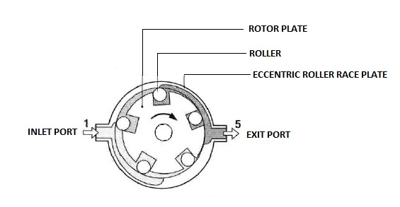
Vane type pump (Low pressure pump):

It sucks the fuel from the tank and supplies it to the high pressure distributor pump. For each rotation, it supplies a constant amount of fuel to the high pressure pump. As the speed increases, the amount of fuel supplied also increases.

Vane pump’s impeller is mounted on the inside of the drive shaft through a key and keyway arrangement. The drive shaft runs the impeller. Impeller is surrounded by an eccentric ring which is mounted in the pump housing. An impeller has 4 floating blades which float outwards against the eccentric ring.


As the drive shaft rotates the impeller, the floating blades are pressed outside against the eccentric ring as a result of centrifugal force. Fuel from the tank flows through the inlet passage provided in the housing and is collected in the chamber formed by the impeller, any 2 floating blades and eccentric ring. As the shaft keeps rotating, the fuel in the chamber is transferred to a constricted space. As a result of this, fuel is pressurized to a margin of 4 bar at idling speed and 10 bar at maximum speed of engine. The low pressure fuel then escapes out through the spill port.


Due to the shape of eccentric ring, the volume of the chamber in which the fuel is collected is reduced when it rotates to the fuel discharge side. This arrangement pressurizes the fuel.
Both the fuel inlet side and fuel discharge side has kidney shaped cells. The inlet side has the fuel inlet bore connected to the fuel inlet passage and the discharge side has the spill port which supplies fuel to the high pressure pump.


Pressure Control Valve (PCV):

As the speed of the drive shaft increases, the pressure generated by the vane pump also increases. This pressure governs the functioning of the hydraulic timing device. Therefore it is important that the pressure generated should not exceed the optimum pressure.


A pressure control valve is used to control the internal pressure. It consists of a spring loaded valve. When the internal pressure is beyond a set value, then the valve plunger is pushed against the force of the compression spring. As a result, the return line is exposed and the fuel escapes through the return line. This reduces the internal pressure. The return line is placed adjacent to the fuel discharge side of the vane pump.

The fuel that escaped through the return line is directed back to the fuel inlet side of the vane pump through an internal passage. The opening pressure of the spring loaded valve can be adjusted by varying the spring tension.

DISTRIBUTOR PUMP DESIGN:

The distributor pump has a compact body in which various parts are integrated together. A typical distributor pump is made of the following components:

  •    Vane pump (Low pressure pump)
  •     High pressure distributor pump
  •      Mechanical governor
  •      Hydraulic timing device
  •      Solenoid shut off valve

HIGH PRESSURE DISTRIBUTOR PUMP:

The high pressure pump has one plunger or piston that pressurizes the fuel and then distributes it to individual cylinders through high pressure fuel lines and nozzles. The fuel is delivered at the specified timing and quantity. The distributor pump consists of the following components:

·         Distributor Plunger/Piston:
The rotational motion from the drive shaft is transferred to the plunger via a roller ring assembly, cam plate and yoke assembly. So the entire unit rotates at the same speed. The cam plate provides the reciprocating motion to the plunger. A plunger has vertical grooves equal to the number of cylinders in an engine. The vertical grooves act as fuel inlet passage to the barrel during inlet stroke of the piston. The stroke movement of plunger is 2.2 to 3.5 mm depending on the type of pump.


The plunger moves to Top Dead Centre (TDC) and compresses the fuel. Two symmetrically arranged plunger return springs push the plunger back to Bottom Dead Centre (BDC) after fuel compression has taken place. The plunger has a fuel delivery line running through its length and this line is connected to the distributor port and spill ports.


·         Cam Plate:


Cam plate has cam profiles which help in plunger reciprocation. The number of cam profiles is equal to the number of cylinders in an engine. The design of cam profiles affects the injection pressure and the injection duration.

·         Distributor Body:


The plunger and barrel are precisely fitted into the distributor body. The plunger also has a control collar which covers and uncovers the spill port to vary fuel quantity. The barrel has distributor slots in its inner circumference which supply fuel to the respective injectors via delivery valve. The distributor body also has a electric shut off valve to block the supply of fuel to the barrel when engine is switched OFF.


FUEL METERING INSIDE THE DISTRIBUTOR BODY:
The distributor body generates the pressure required for fuel injection. There are several phases of plunger stroke for precise fuel metering to take place.

·         Intake stroke:

When the piston moves from top dead centre (TDC) to bottom dead centre (BDC), one of the vertical grooves match with the fuel inlet passage and thus the fuel enters the plunger barrel.

·         Pre-stroke:

As the plunger keeps rotating, it closes the inlet passage. Now the piston starts moving from BDC to TDC and some amount of fuel flows back to the inner chamber of the pump through a slot provided at the top of plunger (also known as pre-stroke groove). Pre-stroke is necessary to prevent slow rise in injection pressure.

·         Effective stroke:

As the plunger moves further up towards TDC, the pre-stroke groove is closed and the injection pressure increases rapidly due to compression. The fuel is delivered to the delivery slot and then supplied to the delivery valve. The delivery valve lifts from its seat and allows the fuel to escape to the injector.

·         Residual stroke:

The effective stroke is complete when the spill port at the bottom of the plunger is exposed. This allows the fuel to escape to the pump’s internal chamber and thus the pressure inside the barrel is releases and there is no more fuel delivery to the injector.

VARIABLE SPEED GOVERNORS:
Variable speed governors are used to control the engine speeds from start to intermediate speed range and also controls it at high speeds. Speed variation is achieved by varying the fuel quantity.

Design:

The design is pretty much different compared to the one in Inline Fuel injection pumps. It consists of a flyweight housing with 4 flyweights. The flyweight housing has a gear at the bottom which is meshed with the drive shaft. It is mounted in its position with the help of a governor shaft. As the flyweights rotate, the movement is transferred to the sliding sleeve which slides up against the starting lever of the governor.


The governor mechanism consists of a starting lever, control lever and tensioning lever. At the end of the starting lever is a ball pin which engages with the control collar of the distributor plunger. A starting spring is attached to the top of the starting lever. There is an idle speed spring attached to the retaining stud at the top of the tensioning lever. A governor spring is attached to the retaining stud on one end, whereas the other end is connected to the rotational speed control lever via a linkage. The rotational speed control lever is linked to the accelerator pedal.


The governor spring tension and the flyweight force transfer the movement to the ball pin. The movement of the ball pin moves the control collar to vary the quantity of fuel delivered to the injectors.

The fuel quantity varies at different speeds. This is done with the help of a variable speed governor.

·         Starting speed:


When the engine is not running, the distributor pump doesn’t supply the fuel to the injectors and the flyweights and sliding sleeve of the governor rests at base position. At this point, the starting spring pushes the starting lever into its position and the movement is transferred to control collar which is brought to starting position. The effective stroke of plunger during position is higher. This allows maximum fuel to be delivered to the engine for starting. For starting the engine, the rotational speed control lever is pressed against the maximum speed screw.

·         Idle speed:

The starting lever force is overcome by a slight increase in engine speed. As the speed starts increasing, the flyweights’ radial movement results in the axial movement of the sliding sleeve which presses the starting lever against the force of starting spring. This results in the movement of control collar bringing it to idle speed position. The effective stroke is minimum for idling speed and this results in lesser fuel delivery to the injectors. The accelerator pedal is released and the rotational speed control lever rests against the idling speed screw.

The idle speed spring mounted in the retaining stud maintains a state of equilibrium with the flyweights’ force and maintains the starting lever in its position. This allows a steady amount of fuel to be delivered to the injector.

·         Operation under load:

When the accelerator pedal is pressed, the rotational speed control lever assumes a position between idle speed screw and maximum speed screw. When the speed of the engine goes beyond the idling speed, the starting spring and the idling speed spring are fully compressed and have no control over the movement fuel flow in this range.

The governor spring has the control over this speed range. When the accelerator pedal is pressed, the rotational speed control lever moves from its idle speed position to a position corresponding to the speed. This compresses the governor spring and the governor spring force exceeds the flyweights’ centrifugal force. As a result, the starting lever rotates and transfers the movement to the control collar. The effective stroke is increased and more fuel is delivered to the engine, thereby increasing the speed.

When the accelerator pedal is fully pressed (Wide open throttle), more amount of fuel is delivered as a result of governor spring’s control over the starting lever. As the speed increases, the flyweights’ centrifugal force increases and the sliding sleeve moves to oppose the spring force. The control collar remains in its wide open throttle position until the opposing forces between flyweights and governor spring achieve equilibrium.

If the speed of the engine further increases, the flyweights’ centrifugal force overcomes the governor spring force and reduces the effective stroke of plunger, thereby leading to speed reduction. Further increase of speed will lead to fuel being cut off

·         Engine Overrunning:
One of the features of a variable speed governor is to prevent overrunning of engines while descending a slope or a hill. The engine is driven by vehicle’s inertia. At this point the sliding sleeve presses against the starting lever and tensioning lever. The starting lever rotates in its axis to transfer the movement to control collar, wherein the collar brings the effective stroke to minimum or zero (in case engine is switched OFF).