Showing posts with label Electricals. Show all posts

Sunday, 30 August 2020

Knock sensors

The term 'Knock' refers to abnormal combustion in SI engines. This occurs due to spontaneous ignition of the air-fuel mixture inside the combustion chamber. This undesirable combustion leads to a higher mechanical load on the engine. High amount of knocking can lead to damage of engine parts such as piston and cylinder.

Knocks can also occur due to overheating of the engine and poor quality of air-fuel mixture.

Knocking generates oscillations with characteristic frequencies. The purpose of a knock sensor is to detect these frequencies and transmit these signals to the engine control system, where the control system evaluates the signal and identifies the extent of knocking. The engine control system then regulates the combustion process (such as advancing the ignition timing by a few degrees) to eliminate knocking.

Knock sensors are generally broadband knock sensor. It covers a frequency spectrum, from 3 to 20 with an intrinsic resonance of over 30 kHz. The knock sensors are placed at appropriate positions in an engine block. Multiple sensors are used in a multicylinder engine (such as 2 sensors in 6 cylinder engine).

Working:

Knock sensors work based on piezoceramic ring that converts vibrations into electric signals using a superimposed seismic mass.


Sensor sensitivity is measured in mV/g or pC/g and is practically constant over a wide frequency range. The transmission behaviour of the sensor can be varied by the choice of seismic mass.

The resonance frequency can be increased by reducing the seismic mass. 

In some cases, knock sensors are also used in CI engines to control the fuel injection timing and the function of injection nozzles.

Types of Knock sensors:

The most commonly used knock sensor is the above mentioned piezoelectric sensor which converts vibrations into electrical voltage. A typical voltage signal is between 300 millivolts to 500 millivolts. The voltage signal is transmitted to the control system which in turn regulates the ignition timing and air-fuel mixture.

An acoustic sensor is often used in vehicles to detect knocking. It employs a small microphone positioned against a cylinder block and detects vibrations. The vibrations are converted into electrical voltage by the microphone and sent to the control unit.

An ion sensor is used in some top end models such as BMW, Ferrari and Mercedes Benz. This type doesn't employ any sensor. It uses spark plugs to detect knocking. By applying an electric current across a couple of spark plugs during the ignition process, a change in the conduction of voltage can imply the status of combustion. 


Friday, 9 December 2016

Ignition System

Ignition system is a device used to create high voltage electrical supply necessary for the spark plugs to create a spark. The spark produced is used to ignite air-fuel mixture in Spark Ignition engines.

Functions of an Ignition System:

·         It must create a high voltage (greater than 20000 V) from a 12 V battery supply.
·         It must control the timing so that spark is created at exactly the right time in all the spark plugs and also in the right cylinder based on the firing order. For a 4 cylinder engine, the typical firing order is 1-3-2-4.

Types of Ignition System:

The basic principle of working of ignition systems hasn’t changed much over the years. Modern day automobiles have one of the 3 types of ignition system:

·         Distributor or Mechanical Ignition System
·         Electronic Ignition System
·         Distributorless Ignition System

In this article, we will talk about the working of Distributor type ignition system.

Distributor type Ignition System:

As the name suggests, it consists of a distributor located at the nerve centre of the ignition system. The distributor triggers the ignition coil to generate the required high voltage. A distributor cap with a rotor is provided which directs the high voltage supply to the spark plug lines in firing order.


How is the high voltage supply generated?

When the ignition key is switched ON, a 12 V electrical energy is supplied from battery to the ignition coil via a primary resistor. The ignition coil has primary copper windings of more than 100 turns before exiting the negative terminal of the coil.

From the ignition coil, the current is supplied to the distributor which has two contact breaker points. One of the contact breaker points is fixed, while the other is movable and mounted on a spring loaded arm. The spring loaded arm rides on a distributor cam with lobes (number of lobes = number of cylinders in an engine). The speed of the cam is half the speed of the engine crankshaft.

When the two contact points are in contact, the current goes directly to the ground and this builds a strong magnetic field inside the ignition coil. The rotation of cam intermittently opens and closes the contact points. When the points are open, the current supply to the ground is interrupted and the magnetic field suddenly collapses in the coil. This collapse in magnetic field results in a surge of electrical voltage in the secondary winding. The high voltage supply is then supplied to the distributor cap via high tension wire.


Ignition Switch:

There are two wires leading to the primary winding of the ignition coil from the ignition switch. Primary wire is connected to the primary winding via a resistor and the secondary wire is directly connected to the primary winding.

When the engine is cranked, the secondary wire is used in order to supply more voltage for easy cranking of the engine. Rest of the time, primary wire is used to step down the voltage using the resistor to protect the contact points from premature wear.

Ignition Coil:

The ignition coil acts as a transformer, stepping up the voltage whenever there is a drop in the magnetic field. It consists of two windings. Primary windings are made of 100 to 200 turns of copper wire. The copper wires must be insulated in order to prevent shorting within the primary coil. The primary winding coils start at the positive terminal and loop their way around and exit out of the negative terminal. The negative terminal supply is given to the distributor.

Secondary windings contain 20,000 to 30,000 turns of copper wire. These wires also must be insulated to prevent internal shorting. The secondary winding sits inside the loop of the primary winding without any contact between them. To increase the magnetic field of the coil, the secondary winding is wound around a soft iron core.

Distributor:

Distributor consists of a cam at the center with lobes equal to the number of cylinders in an engine. The cam controls the opening and closing of the contact breaker points. A condenser is provided which acts like a capacitor to store current for a brief period of time.

The inclusion of a condenser is of prime importance to prevent premature wearing of the breaker points. When the points are open, the current supply to the ground is blocked. Therefore, the current looks to go to an alternative route. Without a condenser, the current would try to jump across the small gap between the points to produce arcing and this would burn up the points quickly. Condenser helps in storing the current and thereby preventing point arcing.

The gap between the points is crucial to run the engine at higher efficiency. The gap can be adjusted by adjusting a screw. The points are continuously subjected to wearing due to the rotation of cam. The points have to be replaced every 15000 to 20000 km depending on the amount of wear.

Distributor Cap:

The spark timing is taken care by the rotor spinning at the top. The secondary winding HT coil is connected to the rotor which spins inside the cap. The rotor spins past a number of contacts provided along the circumference of the cap. These contacts are arranged in firing order along the circumference. The contacts have a HT coil that supply high voltage electricity to the respective spark plugs.

Once the rotor comes in proximity to the contacts, a high voltage current generated in the ignition coil is supplied to the rotor. As the rotor and contact are in proximity, the high voltage current jumps across the gap and passes on to the respective spark plug. The high voltage current then generates spark at the tip of the spark plug, thereby initiating ignition in the respective cylinder. The rotor then spins away and moves to the next contact in firing order.

The contact points in the cap can wear out in time due to the repeated arcing between rotor and contacts. The electrical insulation of the HT coil can also wear out in time and needs to be replaced.

Ignition Timing:

Ignition timing is an important parameter to make sure that the engine is running efficiently under all conditions and loads. The ignition timing needs to be advanced when the speed of the engine is higher, so that even before the piston reached TDC, air-fuel mixture is burned and ready to push the piston down with greater energy and hence producing greater power.

The timing can be advanced either by spinning the plate on which the contact breaker points are attached or by rotating the cam. Ignition timing can be adjusted with two known mechanisms, namely:

·         Centrifugal advance
·         Vacuum advance

Centrifugal Advance Mechanism:

It consists of two centrifugal weights attached to a shaft hinged to the lower part of the distributor cam shaft. The weights are held to the lower shaft due to a spring force. Each weight has a spring attached to it.


As the engine speed increases, the speed of the distributor shaft also increases. The weights overcome the spring tension and start pulling out due to centrifugal force. The weights change the alignment due to centrifugal force and also force the cam to rotate and alter the ignition timing.

Vacuum Advance Mechanism:


Vacuum advance mechanism controls the movement of the distributor plate to which the points are attached. A vacuum diaphragm is connected to the plate on which the contact points are mounted. Vacuum is created by the engine inlet manifold. When the throttle pedal is not pressed, no vacuum is created. When the throttle pedal is pressed, vacuum is created which advances the timing.


Wednesday, 2 November 2016

Spark Plugs

Spark plug is a device used commonly in Spark Ignition (S.I) engines to ignite the air-fuel mixture in the combustion chamber. It produces electric spark when current is passed by the ignition system.

Gottlob Honold of Bosch developed a spark plug that helped in the development of spark ignition engines in 1902. Later in 1903, Oliver Lodge developed a more reliable version of spark plug to fit in S.I engines.

When does a spark plug fire?

We all are aware of the four strokes of S.I engines. At the end of compression stroke, the pressure build up in the combustion chamber becomes intense. The fuel breaks into finer particles due to the compression of charge. This is the easiest time to ignite the fuel and hence spark plug is excited by the ignition system to generate an electric spark that generates enough temperature to ignite the air-fuel mixture.

Spark plug is installed at the top of the cylinder head and ignites when the piston reaches top dead centre (TDC) in the compression stroke.

Functions of a Spark Plug:

A Spark plug basically has two main functions:

·         To ignite the air-fuel mixture. The electric energy passes through the central electrode and jumps the gap at the tip to generate spark, which then ignites the air-fuel mixture.

·         To dissipate the heat from combustion chamber. We might be at a misconception that spark plug creates heat, but no. Spark plugs act as a heat exchanger remove the heat from combustion chamber and transferring it to the cooling system. The temperature at the tip should be maintained such that it should not be high enough to lead to pre-ignition and it should not be low enough to result in fouling.


CONSTRUCTION OF A SPARK PLUG:

Insulator Body:

Insulator body is made of aluminium oxide ceramic. The shape of the body is moulded in a dry moulding system. After it is dry moulded, it is heated to a temperature higher than the melting point of steel. This provides high thermal conductivity and shock resistance. The surface is ribbed for better grip and protection from secondary voltage.

Terminal:

It is also known as connector. This is where the spark plug wire from the ignition coil is connected to the central electrode.

Hex Head:

This part is to fit the socket wrench in order to tighten and loosen the spark plug in its hole in the cylinder head.

Shell:

Shell is made of steel and is fabricated with the help of cold extrusion process. The shell is plated for corrosion resistance.


Gasket:

Gasket is used for sealing purpose. Threads are provided to screw the spark plug in the cylinder head.

Central Electrode:

The central electrode is connected to the outer terminal. It is an internal wire that conducts current from outer terminal to its tip. The tip is usually made of copper to carry away the heat of combustion.

Ground or Side Electrode:

They are manufactured from nickel alloy steel. They have an edge shaped area at the bottom to create the gap between central and side electrode. The high voltage jumps from the central electrode to the side electrode to create the required spark.

Spark Plug Working:

The high voltage required to generate a spark is supplied by an ignition coil. As the electrical energy passes through the central electrode, a voltage difference is created between the central electrode and the ground electrode. We all know that spark plug is fitted at the top of the cylinder head. Hence, air-fuel mixture will be present in the gap between the two electrodes.

Air-fuel mixture acts as an insulator, therefore no current can flow between the electrodes. Once the voltage is high enough to exceed the dielectric strength of the air-fuel mixture, the mixture is ionized. Ionized gases act as a conductor and allow the electrons to flow through them, thereby creating a spark. Different spark plugs require different voltages to generate the spark. It usually ranges between 20,000 V to 1,00,000 V.

A small flame is created at the tip of the spark plug which then flows as a flame front at the top of the piston depending on the composition of air-fuel mixture.

Types of Spark Plugs Based on Temperature:

Spark plugs can be divided into two types: Cold plug and Hot plug.

·         Cold Plug: Cold plugs are used in engines that generate high horse power and high compression pressure and temperature. It has less insulation; therefore it can transfer more heat from combustion chamber to the cooling system. It is of prime importance to transfer the excess heat from the combustion chamber to the outside in order to prevent pre-ignition and engine damage.

·         Hot Plug: Hot plugs have more insulation compared to cold plugs. These plugs are available in most standard engines. These spark plugs retain more heat to burn off the excess carbon deposits.

What is Spark Plug Fouling?

Fouling is known as coating of the insulator tip with foreign particles such as oil, carbon or fuel. This allows the high voltage to leach back down to the metal shell and to the ground instead of jumping the electrodes gap and creating spark.


Wednesday, 16 March 2016

Alternators in Automobiles

The demand for power supply in automobiles has been increasing steadily over the years. It is estimated that the power output from an alternator has increased 5 times in a span of 30 years from 1950 to 1980. The demand for power supply is going to increase at a higher rate in the future. This need will rise due to the new technologies which rely completely on electronics such as the ECUs, safety equipments, navigation system, etc.
Alternator (also known as generator) is the main power generating device. Alternators should not only withstand the higher load demand, but also be quieter in operation and have a long life. The electronic voltage regulators are a must to withstand the fluctuations in loading and also engine speed changes.
Alternators are an energy generating device that meets the constant energy demands of the fuel injection system, ECUs, safety equipments, lighting, etc. Alternators are also used to recharge batteries. It is a highly reliable source of energy which supplies energy at anytime, provided the engine is running.
Generation of Electrical Energy in Automobiles:
When the engine is stopped, battery acts as the energy source. Whereas, when the engine is running, alternator is the energy source. Alternators function is to supply electrical energy to the systems necessary for operation. Energy supply can be based on the driver’s needs (for e.g. lighting) and also systems which require continuous supply irrespective of the driver’s command (for e.g. ECUs and sensors).
It is necessary that the alternator power output is optimally matched with the battery capacity, starter motor requirements, and other electrical loads. For example, in a normal driving condition, the following points should be considered for smooth operation:
  • Battery should always have enough charge at any given time to supply power to the starter motor to crank the engine, irrespective of temperature.
  • The ECUs, sensors and actuators should always be ready for operation. For example, ignition, Fuel injection, Anti-lock Braking System (ABS), Traction Control System (TCS).
  • Vehicle safety system must operate immediately, such as air-bags, ABS.
  • Lighting system to operate at nights and in foggy conditions.
  • When the vehicle is parked, a number of electrical loads must continue to operate without draining the battery too much so that there is enough charge to start the engine again. For instance, Anti theft system is mostly in operation when car is parked.
Electrical Loads:
Based on the requirements, there are 3 different types of electrical loads:
  • Permanent loads such as ignition, fuel injection, ECUs.
  • Long duration loads such as lighting, music system, Air-conditioners.
  • Short duration loads such as horn, turn indicators.
Vehicle Electrical System Layout:
The layout of wiring of electrical equipments, alternator and battery can make a significant difference to the voltage output of alternators and also the state of charge of the battery.


  • If all the electrical equipments are connected to the battery, then there is a reduction in charging voltage to the battery due to high voltage drop. This is due to the cause that both the battery charging current and electrical load current pass through the same charging line, thereby resulting in voltage drop.
  • If all the electrical equipments are connected to the alternator side, then charging voltage to the battery is higher and at the same time voltage drop to the electrical equipments is lesser. But this can harm electrical devices which cannot withstand high voltage peaks.
  • The best way to deal with the above problems is to connect the high voltage sensitive equipments to the battery and the insensitive equipments to the alternator.
Working Principle of Alternators:
The availability of power diodes paved the way for the series production of alternators. Bosch started with the series production of alternators around 1963. The working principle of alternator makes it far more efficient than the DC generators.
Alternators work on the principle of electromagnetic induction. When an electric conductor (Wire or a wire loop) cuts through the lines of magnetic forces of DC magnetic field, a voltage is induced in the conductor. In the case of alternators, magnetic field rotates inside the stationary conductor.
Electromagnets are used to generate magnetic field inside the conductor. Electromagnetism is based on the fact that when an electric current flows through a wire or winding, it generates electromagnetic field around them. The number of turns in the winding and the magnitude of current flowing through the winding determines the strength of magnetic field. An iron core is used to further strengthen the magnetic field, which when rotates induces an alternating voltage in the winding. Single phase alternators have only one winding in the armature.
Principle of operation of a 3-phase Alternator:
3 phase alternators work on the same principle as the single phase alternators, except that they have three windings in the armature separated at an angle of 120° from each other. According to the law of induction, voltage is induced in each of the three windings of same magnitude and frequency. The only difference is that these sinusoidal voltages are 120° out of phase with each other. Therefore, a 3 phase alternator develops constantly recurring 3 phase alternating voltage.
It would normally require 6 wires, 2 wires each for a winding to transfer the voltage generated. To reduce the number of wires to 3, the 3 windings are interconnected forming a ‘Star’ connection or ‘Delta’ connection.
In an automotive alternator, the 3 phase winding with iron core acts as the stationary component, so it is also known as ‘stator’ winding. Whereas, the electromagnet or the excitation winding acts as a rotor. When the rotor rotates, its magnetic field induces a 3 phase alternating voltage in the stationary winding.
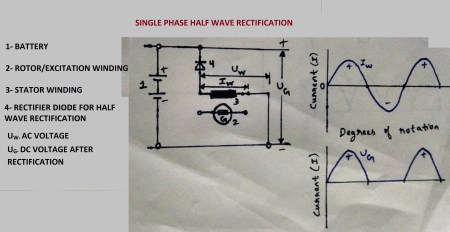
Rectification of Alternating Voltage:
All the electrical components of a car can operate only on direct current (DC). Even the battery cannot store Alternating current (AC). Therefore, the current from the alternator has to be rectified with the help of power diodes (Zener diodes) that can operate over a wide range of temperature.


The power diodes or rectifier diodes have forward and reverse direction. It works like a non-return valve, which allows current in one direction but blocks in the reverse direction. The diodes allow only positive half waves to pass through, suppressing the negative half waves. These results in a pulsating DC, also known as half wave rectification. Full wave rectification can be applied wherein both positive and negative half waves are rectified.


Bridge Circuit for 3 phase AC rectification: 


3 phase AC generated in the 3 phase winding is rectified with the help of 6 diodes. Two diodes for each phase, one on the positive side and the other on the negative side. The positive half waves pass through the positive side and the negative half waves pass through the negative side, and rectification takes place.  
Excitation Current: 
The excitation current required to magnetize the rotor is initially drawn from the battery. The current passes through 3 exciter diodes and then towards the rotor. Once the magnetized rotor starts rotating inside the 3 phase winding, AC is induced in the stator. Now the excitation current can be tapped from the winding and the battery is no longer a source of current for excitation.
Reverse Current Block: 
The rectifier diodes not only rectify AC, but also prevent the battery from discharging through the 3 phase winding. The diodes prevent the current flow from battery to alternator. When the engine is stopped or running at low speed, the current in the battery would discharge without the diodes in their place.
ALTERNATOR DESIGN:
Claw pole alternator is the most commonly used alternator in modern vehicles. The construction of this type is as follows:
  • 3 phase stator winding with a solid laminated iron core pressed together. The turns of the windings are embedded in the grooves of the iron core.


  • Rotor on which two claw shaped poles are mounted, and excitation winding is enclosed between the 2 poles. A fan is mounted on both the ends. Two collector rings are provided on the shaft which draws excitation current from the diodes via carbon brushes. Fans must be designed based on clockwise rotation or anti-clockwise rotation.


  • Pulley is mounted on one end of the rotor shaft. Rotors can rotate in both the directions.

  • Rectifier has at least 6 power diodes which are embedded in the heat sink.

  • Collector end shield is provided at the end where rectifier is placed. It acts as a cover.

  • Drive end shield is provided at the pulley end. Stator is enclosed between the two end shields.

  • Electronic regulator along with Carbon brush holders form a single unit.

Design Criteria: 
An alternator is designed based on the following criteria:
  • Vehicle type
  • Operating conditions
  • Engine speed range
  • Power requirements of the electrical equipments in a vehicle
  • Battery voltage
  • Available Space
Features of a Claw Pole Rotor:


  • The claw pole rotor has excellent heat dissipation quality.
  • The claw shaped poles face each other in rotor shaft, where the pole fingers mesh with each other to form alternating north and south pole which envelop the excitation winding.
  • Lower number of poles means lower efficiency. Higher number of poles results in more amount of magnetic leakage.
  • Alternators have 12 or 16 poles based on energy demand.

WORKING OF AN ALTERNATOR:
When the rotor (12 pole rotor) is excited, magnetic flux is induced in the left hand claw pole and its fingers. The magnetic flux flows through the air gap to the stator winding, and then returns to the right hand claw pole side, hence completing the circuit. This magnetic field of force cuts through the 3 phase stator winding and after one complete revolution (360°), 6 sinusoidal waves are generated in each phase.


The generated current is divided into primary current and excitation current. The primary current is rectified and then supplied to the battery and other loads. The excitation current is sent back to the rotor as rotor requires continuous supply of current for excitation.
Pre-Excitation Circuit: 
When the engine is started, it runs at a low speed. There is not enough residual excitation current to build up magnetic field in the rotor. Therefore, self excitation doesn’t take place and there is no output current from the alternator.
Battery is used as the source for the excitation current. The current (IB) flows through the charge indicator lamp, and then to the rotor. It generates magnetic field in the rotor which in turn generates output current in the stator proportional to the rotor speed.


Once the engine gains speed, the self excitation current from the alternator should exceed the voltage drop across the excitation diodes to enable self excitation of the rotor. Once self excitation occurs, the supply from the battery is blocked with the help of charge indicator lamps. Once the generated voltage from the alternator exceeds the battery voltage, the charge indicator lamp resists the flow if current from the battery to the rotor.
Excitation Circuit: 


It is the duty of the excitation current to magnetize the rotor during alternator operations. The self-excitation current (Ierr) is tapped from the 3 phase stator winding. The self excitation current flows through the excitation diodes, carbon brushes, collector rings, and to the excitation winding in the rotor to generate magnetic field. It flows further to the terminal DF of the regulator and flows out through (D-), and further to the ground (B-).
Actual Alternator Current Flow Circuit:


The output AC voltage generated in the stator winding is rectified with the help of power diodes (B+) and converted into DC current (IG) which flows to the battery and other loads. Simultaneously, the self excitation current (Ierr) used to generate magnetic field in the rotor is tapped from the stator winding. The cycle is repeated again and again.
VOLTAGE REGULATORS:
A regulator maintains the alternator output voltage over a wide range of alternator speed, independent of engine speed and vehicle loads. Maintaining a constant alternator voltage will prevent the damage of high voltage sensitive devices and also prevent the battery from overcharging. The alternator voltage may vary slightly based on temperature. In cold conditions, the alternator voltage is slightly higher because it is difficult to charge batteries at low temperatures.
The voltage output from the stator depends on the magnetic field generated by the rotor. The magnetic field strength can be varied by varying the flow of excitation current flowing to the rotor. Voltage regulator helps in varying the flow of excitation current to prevent the voltage output to exceed a set value.


Contact regulators have a movable contact point which is pressed against a fixed contact point by a spring. This contact regulator is of a single element type. It comprises of a regulating contact, an electromagnet and a regulating resistor. When the output voltage is beyond a set value, the electromagnet pulls in the armature and opens the circuit. This excites the resistor which restricts the flow of excitation current to rotor and thus the output voltage drops. When the output voltage falls below the set limit, the electromagnetic force lessens and the spring presses the movable contact towards the fixed contact, thus closing the circuit and allowing the excitation current to flow through.
Voltage regulator characteristics:
  • Shorter switching time
  • Insensitive to shock and vibration
  • No wear
  • Compact in size

Friday, 4 March 2016

Engine Immobilizer

Engine immobilizer is an anti-theft security system installed in a vehicle to prevent the vehicle from starting the engine unless the right key is present. It prevents the vehicle from theft by old methods such as hot wiring. Honda was the first vehicle manufacturer to commercially introduce engine immobilizer system in its vehicles in 1990.

This system uses a key which has a unique code on a transponder chip installed in it. Once you insert the key in the ignition switch, the chip transmits the unique code to the vehicle. The vehicle ignition will only start when the transponder chip code in the key matches the code in the engine immobilizer. The Electronic Control Unit (ECU) won’t activate the fuel supply system and the ignition system if the code in the key does not match the code in the immobilizer.

Some modern cars have keyless ignition switch (start-stop button). These cars have a smart key fob which transmits the code to the vehicle and then to the immobilizer.

When the key is inserted, the internal circuit in the key is activated by an electromagnetic field. As a result, current flows through the circuit and carries the unique binary code to the ECU. The ECU after verifying the codes, activates the fuel supply and ignition systems.

Friday, 26 February 2016

Lead Acid Battery

The demand for power is rising continuously in automobiles. Starter motors, increasing number of electrical devices are demanding more input from the battery and alternator. Vehicle’s energy sources, battery and alternators face several challenges such as:

  • High power demand at extreme weather conditions (at cold temperatures, electrical devices demand higher power supply).

  • To have higher load capacity at low speeds.

  • Smooth operation at high loads.

  • Undisturbed power supply at all conditions to safety systems (ABS, Traction control, etc.)

Battery principle:

A chemical reaction between the electrodes and electrolytes generate electricity. Battery is the storage unit for the electricity and supplies it to the vehicle loads based on the demand. The supply of electricity discharges the battery; therefore it requires an external source to recharge itself. Alternator recharges the battery by supplying current.

Starter motor has the highest current consumption of all the loads, even though for a small period of time. This is due to the fact that the suction, compression and exhaust strokes provide a lot of resistance to the crank movement. Therefore, higher power supply is required to overcome the resistance and crank the engine.

Battery supplies power only under these circumstances:

  • When the engine is OFF: To crank the engine and also to supply power to other electrical loads such as lighting, music, etc.

  • When the engine is ON: Once the engine is cranked, alternator not even meets the power demand of the loads, but also charges the battery. When the engine is running at idling speed or lower speed, the battery must be able to supply power to the electrical devices for a brief amount of time. Also when the power demand overcomes the alternator supply capacity, the battery assists in meeting the demand.

 BATTERY OPERATION: 

The battery must have enough energy to start the engine, especially at low temperatures. When the engine is started, the battery takes the role of electrical energy storage unit to store the current produced by the alternator. This energy is used to start the engine again next time after it has been switched off.

The battery also absorbs peak voltage to protect the sensitive loads from damage. Typically, a Lead-Acid battery is used in automobiles, which is enough to meet the energy demands. A 12V battery is used in light commercial vehicles (for e.g. Cars) and 24V battery is used in heavy duty vehicles (for e.g. Trucks).

Design:

It consists of two electrodes of different materials PbO2 (Lead peroxide) and Pb (Lead) dipped in an electrolyte solution of dilute H2SO4 (Sulfuric acid) of density 1.28 kg/l. Both the electrodes have different potentials when immersed in the electrolyte. The difference in potential between the electrodes is known as the cell voltage.

The PbO2 electrode is the positive electrode (cathode) and Pb is the negative electrode (anode). The entire setup where the two electrodes are immersed in an electrolyte is known as a cell. Two or more cells arranged in a series in known as a battery. A cell generates 2V. In a 12V battery, six cells are arranged in a series.

Battery Discharge (Generation of Current):

When load is applied, electrons flow from the negative electrode (Pb) to the positive electrode (PbO2). The flow of electrons is known as current and this current is passed to the load (for e.g. a lamp bulb placed in between the 2 electrodes starts glowing due to electron flow).

Cell discharge reaction

As a result of this electron flow, the bond between lead and oxygen atoms is broken. The lead at positive electrode becomes bivalent positive ions (Pb2+) and oxygen becomes bivalent negative ions (O2-). The electrolyte (H2SO4) separate into sulfate ions (SO42-) and hydrogen (H+). Meanwhile, the negative electrode Pb is converted into bivalent ions (Pb2+).

The lead (Pb2+) and sulfate ions (SO42-) combine at both positive and negative electrodes to form lead sulfate (PbSO4). The oxygen ions (O2-) combine with hydrogen ions (H+) to form H2O (water).

Battery Charging:

Battery charging process is the inverse of the discharging process. Current is supplied to the battery from an external source (alternator). The current flows in reverse direction, from positive electrode to the negative electrode. As the electron flows into the negative electrode, the lead sulfate (PbSO4) molecules are broken down. As a result, the bivalent lead (Pb2+) is converted to Pb. The sulfate ions (SO42-) are released into the electrolyte.

Cell charge reaction

At the positive electrode, the lead sulfate (PbSO4) molecules are broken down and tetravalent lead (Pb3+) is formed. The sulfate ions (SO42-) are released into the electrolyte.

The water molecules (H2O) in the electrolyte are broken down into H+ and O2- ions. The hydrogen ions (H+) and sulfate ions (SO42-) combine to form dilute sulfuric acid (H2SO4) as the original electrolyte.

At the positive electrode, the bivalent negative oxygen ions (O2-) and tetravalent lead ions (Pb3+) combine to form lead peroxide (PbO2).
Negative plate reaction:

Pb (s) + HSO4- (aq.) ↔ PbSO4(s) + H+ (aq.) + 2e-

Positive plate reaction:

PbO2(s) + HSO4-(aq.) + 3H+(aq.) + 2e- ↔ PbSO4(s) + 2H2O (liq.)

Total reaction:

Pb (s) + PbO2(s) + 2 H2SO4 (aq.) ↔ 2 PbSO4(s) + 2H2O (liq.)

s- solid

aq. - aqueous

liq. - liquid

BATTERY CONSTRUCTION:

A 12 V battery consists of a series of 6 cell packs arranges in a case made of polypropylene material. Each cell pack is made of two lead plates immersed in dilute sulfuric acid. The positive and negative polarity plates are separated by a semi permeable membrane known as the separator. Even the cell terminals, connectors and plate straps are made of lead. Likewise, 5 more cell packs are arranged in a series and the top layer is sealed by a hot molding process.

Battery construction

Each cell pack has a vent plug which allows refilling the electrolyte when the density of electrolyte drops. It also allows the gases in the electrolyte chamber to escape.

Battery Case:

The battery case which is made of polypropylene is acid-resistant. It is provided with partitions to separate the cell packs. The case is provided with a sediment chamber below the lower edge of the cell packs. During electrochemical process, lead accumulates as sediment as a result of plate disintegration. The sediment should not be in contact with the plates in order to avoid short circuit. Therefore, the sediment is collected in the sediment chamber.

The cell packs are connected in series using cell connectors which provide a connection to the cell terminals via an opening through the cover. The positive plates are connected using plate connectors, and the same goes for negative plates. Both positive and negative plates are separated with the help of separators.

Cell Packs:

A battery’s ampere-hour (Ah) capacity can be increased by increasing the number of plates in a cell pack. More number of plates increases the overall surface area of the plates and thus Ah capacity increases. The number of negative plates is usually one more than positive plates.

Plates and separator

The plate is nothing but grid plates made of lead with active materials pasted on them. The active material on the negative plates is made of pure lead in the form of spongy lead (Pb) and it is of metallic grey color. The active material on the positive plates is made of lead peroxide (PbO2) which is dark brown in color.

Separators:

Separators made of polyethylene are a vital part of the battery to avoid short circuiting. The positive and negative plates should never be in direct contact. Separators should be acid resistant and have a micro-porous structure to allow ion migration.

Cell Terminals:

The plate strap of the positive plates should be connected to form the positive terminal in the first cell. The plate strap of the negative terminals in the last cell pack should be connected to form the negative terminal of the battery. As a result, terminal voltage of 12 V is available between the two terminals.

BATTERY TYPES:

Based on the grid material used for the positive and negative plates in a cell pack, a battery can be divided into 3 types:

  • Maintenance requisite batteries

  • Hybrid batteries

  • Maintenance free batteries

Maintenance requisite batteries (lead-antimony alloy):

These types of batteries require regular maintenance to make sure that the battery performs as intended. The grid material used as plates is made of lead-antimony alloy (PbSb). Addition of antimony to lead can make the manufacturers achieve thin grid plates. It provides the strength to withstand operations at extreme conditions.

There are various disadvantages of using antimony with lead as grid plates. They are:

  • Due to corrosion at positive plates, the antimony molecules are separated from the grid plates and start travelling towards the negative plate via separator and electrolyte and starts poisoning it.

  • As a result of the above point, the negative plates start self-discharging at a higher pace.

  • Gassing occurs at lower voltage.

  • As a result of the above factors, the battery starts getting overcharged leading to increased water consumption. This as whole results in increase in the amount of antimony released.

  • The self discharge of the negative plates is one of the prime reasons why starter motors don’t receive adequate current to start the engine.

Hybrid Batteries:

In hybrid type, there are two different materials used for the plates. Lead calcium (PbCa) alloy is used for negative plates and lead antimony (PbSb) alloys are used for positive plates. The positive plates are manufactured using casting process, whereas negative plates can be manufactured using simple drawing process.

Even though the maintenance required for hybrid type is less compared to the previous type, it still does not meet the extreme low water consumption demand because of the presence of antimony.

Maintenance Free Batteries:

  • Lead calcium alloy (PbCa): In this type, both the plates are made of the same grid material. Lead calcium alloy (PbCa) is used as a grid material for the plates. Use of PbCa avoids the poisoning of negative plates because PbCa does not react during electrochemical process. As a result, the self discharge of negative plates can be prevented. It also means that gassing will occur at appropriate temperature. Therefore, water consumption can be kept low and overcharging can be prevented.

  • Lead calcium silver alloy (PbCaAg): In a bid to withstand adverse temperatures, the battery has had a recent development in the alloy used for the grid of positive plates. A small proportion of silver is added to the PbCa alloy and it has proven to be reliable even at higher temperatures.

Tuesday, 23 February 2016

Starter Motor

Before an internal combustion engine can start running and generate power on its own, it requires an external source to make it start running. This work is done by a starter motor. Starter motor provides a certain degree of momentum till the engine generates enough torque in the power stroke to overcome the resistance during suction, compression and exhaust strokes. It requires a large amount of force to start an engine.

STARTER MOTOR DESIGN:

Most of the vehicles today use a reduction gear type starter motor.

Starter Solenoid:

 Starter solenoid has 2 main functions:

  • To move the pinion gear outwards so that it can mesh with the ring gear

  • To complete the starter motor’s primary electric circuit

The solenoid housing consists of a solenoid switch or armature which is movable. There are 2 solenoid windings, named as pull-in winding and hold-in winding. The solenoid switch moves towards the solenoid core, pressed against the return spring. The movable solenoid switch is connected to a contact plate at one end, pressed against the contact spring. The contact plate when comes in contact with the contact switches, completes the starter primary circuit.


                                       Solenoid switch
                                                       Solenoid Switch

The solenoid coil consists of a pull-in winding and a hold-in winding. The magnetic force in the pull-in winding pulls the armature towards the solenoid core. The magnetic pull in the pull-in winding should be high enough to close the air gap between armature and the core. Once the air gap is closed enough, the magnetic force in the pull-in winding is sufficient to hold the armature, and thus the contact plate comes in contact with the contact switches and the primary circuit is completed.

Stator Housing:

 The stator housing consists of a 6 pole permanent magnet which acts as a stator. The armature rotates inside the housing as the rotor. The drive from armature is not directly given to the pinion. A reduction gear assembly having 3 planetary gears takes the drive from the armature. The reduction gears provide high starting torque required to start the engine.

                                 Stator winding
                                                      4 pole stator

The current is transferred from the solenoid switch to the armature via four carbon brushes (two positive and two negative). The armature has a laminated core which is press fitted into the armature shaft. The laminated core has slots along the circumference in which copper wire is fitted. The copper wires are connected to each other in a specific pattern and are welded to the commutator plate. The entire setup is known as armature winding.

The current flows through the carbon brushes which are in sliding contact with the commutator. Due to the rotation of the armature, the current is passed to the individual commutator plates in sequence.

Armature winding

The circuit in the armature winding is arranged in such a way that the current flowing in the copper wires adjacent to the north poles of the magnetic field created by permanent magnets, always flow towards the pinion. Whereas the current in the wires adjacent to south poles, flow in opposite direction (towards the commutator). Since the armature is rotating, the commutator reverses the flow in wires as different commutator plates come in contact with the carbon brushes in a sequence.

Carbon brushes

The flow of current through the armature which is placed in a magnetic field produces a force which rotates the armature. The commutator maintains the torque in the armature. The rotational force or torque is proportional to the current flowing through the armature, the strength of the magnetic field, length of the laminated core, and the diameter of the armature.

Reduction Gear Assembly:

 In a direct drive mechanism, the drive from the armature is directly given to the one way clutch and pinion assembly. In case of cold starting, the engine requires more torque to be started. Therefore, the starter motor size has to be increased to meet the high torque demand.

                  Planetary gear

A reduction gear assembly can achieve higher torque without having to increase the size of the starter motor. A planetary gear assembly acts as the reduction gear. Gear ratios can be varied from 3.4:1 to 6:1 based on the torque requirements. Warm starting engines can start on higher transmission ratio, and cold starting engines require lower transmission ratio.

The planetary gear assembly has a sun gear (drive gear) which is attached to the armature shaft. It has 3 planet gears engaged between the outer gear with internal teeth and sun gear. The outer gear transfers the drive to the pinion.

Overrunning Clutch:

 Overrunning clutch is also known as one-way clutch. It is positioned between the armature and pinion. Its task is to disengage the pinion from the pinion drive shaft as soon as the ring gear starts rotating at a higher speed compared to the pinion. Therefore, one way clutches prevent the armature from over acceleration once the engine has started.


Roller type overrunning clutch is commonly used for commercial vehicle application. It has a clutch shell with roller race. The roller race has cylindrical rollers which are pressed into a constricted space with the help of springs. The clutch shell drives the pinion due to a helical linkage between the shell and pinion shaft.

When the overrunning clutch is at rest, the cylindrical rollers are pressed into the constricted space between the roller race and clutch shell. As a result of this, the rollers are jammed and thus the drive from the armature is given to the pinion. The pinion is forced to rotate when the rollers are jammed.

As soon as the ring gear starts to rotate at a higher speed, it will make the pinion to overrun. At this time, the rollers are pushed to the broader side of the roller race due to friction between pinion shaft and the rollers. Now the pinion is disengaged from the pinion shaft.

STARTER MOTOR OPERATION:

The starter motor starts an engine by engaging its pinion gear with the ring gear, which in turn is meshed with the flywheel. In a typical starter motor, the pinion gear has 10 teeth. The ring gear has around 130 teeth.

When the ignition key is pressed, the ignition switch completes the circuit and current from the battery flows to the starter motor solenoid. Magnetic field is created in the solenoid winding due to electromagnetism. The solenoid winding pulls the solenoid armature, thereby operating the engaging lever which engages the pinion with the ring gear.

Starter motor layout

Under ideal circumstances, the teeth of the pinion would mesh with the teeth of the ring gear. But in most cases, the teeth of both the gears would collide with each other as they try to engage. In this case, the engine cannot be started as there would be no power delivered to the flywheel to rotate the crankshaft. The solenoid armature won’t be pulled in further and the circuit remains incomplete for the current to flow to the armature.

Typically the above solution can be solved by pushing the vehicle forward and this would change the position of the ring gear as the rotation of wheels will make the differential gears to rotate, then the propeller, then the transmission, then the crankshaft and finally rotating the flywheel and ring gear. The engagement is tried again by starting the ignition.


The above solution requires human effort and consumes crucial time. Manufacturers came up with a simple solution to add a meshing spring between the pinion and engaging lever. In this case, when the teeth of both gears collide, the solenoid armature will continue to move in as the meshing spring is compressed by the lever. The circuit is completed and the current flows through the armature. The armature starts rotating due to the rotational force created when a current carrying conductor is placed in a magnetic field. The drive from the armature is given to the pinion, which when rotates brings the pinion teeth to align with the gap in the ring gear teeth and they finally mesh and start the engine.

Use of a reduction gear would increase the torque and the overall size of the starter motor can be kept smaller. The overrunning clutch makes sure that the pinion disengages with the pinion drive shaft once the pinion starts overrunning.