Friday, 15 January 2021

Swirl Flaps in Diesel Engines

The air flow pattern inside the cylinders of a diesel engine has a fundamental effect on mixture formation. The factors that influence air flow pattern are:

  • The air flow generated by injection jets
  • The movement of air flowing into the cylinder
  • Piston movement
The whirl assisted air during the induction process helps in rapid mixture formation with the diesel fuel, which is critical for rapid combustion. With the help of swirl flaps, whirl can be regulated depending on the engine speed and load.


The intake ducts are designed as fill channels and swirl passages to allow the passage for air. The fill channel can be closed with the help of a flap (swirl flap), controlled by the engine management system. The swirl flap is closed at low engine speeds (idling speed) and is fully open at high engine speed and load. Flap can also be at an intermediate position depending on the engine speed. Swirl passages on the other hand don't employ any flap.

At low engine speeds, air is sucked via the swirl passage. The whirl is much stronger as the fill channel is closed. At high engine speeds, the fill channel is opened and this allows far more quantity of air to be inducted into the cylinder. The whirl is not strong when flaps are open.

The control over whirl function makes it possible to cut the NOx and particulate emissions to a significant effect especially at low engine speeds. 

Swirl flaps are used in some car engines and is playing an important role in minimizing emissions. However, modern day trucks have diesel engines that operate at low whirl rates. Due to their smaller engine speed range and larger combustion chamber, the injection jets are sufficient to allow mixture formation.

Thursday, 14 January 2021

Alternative Fuels for Diesel Engines

1. Biodiesel:

Biodiesel is fatty acid esters which are created through cracking of vegetable oils or greases and then converted with methanol or ethanol. If mixed with methanol, it creates fatty acid methyl ester (FAME) and if mixed with ethanol, it creates fatty acid ethyl ester (FAEE). The molecules of biodiesel are similar to diesel fuel in terms of size and properties.

Production of Biodiesel:

Biodiesel are produced from vegetable oils or animal fats. Europe primarily uses rape oil. Soybean oil and palm oil can also be used to produce biodiesel. Esterification of oil is carried out with either methanol or ethanol. Since methanol helps in simpler esterification, it is preferred more over ethanol. Therefore fatty acid methyl ester (FAME) is primarily used worldwide as an alternative biodiesel.

Since methanol is produced from coal, FAME is strictly not fully biogenous. FAEE on the other hand is made up of 100% biomass. The properties of biodiesel are determined by many factors. Different vegetable oils have different composition of fatty acid blocks. The type and quantity of unsaturated fatty acid blocks have decisive influence on the stability of biodiesel. The quality also depends on the pre-treatment of vegetable oils and the production process of biodiesel.

The quality of biodiesel varies from the regular diesel fuel, since biodiesel consists of fatty acid esters which are polar and chemically reactive. Diesel fuel on the other hand is an inert and nonpolar mixture of paraffins and aromatic compounds. 

Use of Biodiesel in vehicles:

Pure biodiesel (B 100) is used especially in Germany in commercial vehicles. The higher mileage ensures fast consumption, which ensures problems with insufficient oxidation stability to be avoided. It is more favourable to use biodiesel in a blend with conventional diesel fuel. The trend is towards small mixtures of 93% diesel and 7% biodiesel (B 7).

The presence of biodiesel in diesel fuel provides lubrication and hence additional lubricative additives are not required. In the case of higher biodiesel content in the diesel-biodiesel mixture (above B 30), the higher boiling point of fuel can cause it to escape to the engine oil via condensation on the cylinder walls. 

2. Rape Oils:

Rape oil can be used in older engines, especially those fitted with inline pumps. It is an inexpensive fuel, but increases emissions and also risks of engine failures.

Limitations:

Rape oil has high density and viscosity and is highly volatile in nature compared to diesel fuel. Direct usage of rape oil affects fuel supply at low temperatures due to the formation of residues on injector nozzles by thermal coking. 

3. Bioparaffins:

Bioparaffins are produced from fats and oils by means of hydrogentaion. Hydrogenation with hydrogen results in cracking of fats and oils, during which the oxygen atoms and other unsaturated bonds are removed. Long chain alkanes are created from fatty acids, while the glycerin is converted into propane gas. The end result is hydrocarbon molecules with better properties for combustion than biodiesel.

The product properties of bioparaffins are far greater than biodiesel. It is also more cost effective than biodiesel to produce bioparaffins because hydrogenation process can take place in petroleum refineries.

4. Synthetic Fuels:

Synthetic fuels are produced from individual chemical blocks. Coal, natural gas or biomass can be thermally converted into synthetic gas made up of carbon monoxide (CO) and hydrogen. Linear, straight chain hydrocarbons, n-paraffins are then produced from CO and hydrogen on Fischer-Tropsch catalysts. Further, isomerization can improve the quality of synthetic fuel, particularly its low temperature resistance.

Synthetic fuels are also called second generation fuels as its production process differs from the common hydrogenation or esterification process on oils and fats.

Fischer-Tropsch synthesis can produce a wide variety of other components such as short chain gasoline, kerosene, diesel paraffins, waxes. The composition of synthetic diesel fuels can be varied on the demands of the diesel engine with the help of catalysts of our choice.

The synthetic fuels produced by Fischer-Tropsch synthesis are purely aromatic and sulphur free. They also have a high cetane number. The density of synthetic fuel is lesser than the conventional diesel fuel at 800 kg/㎥.

Due to its lower HC, nitrogen oxide and CO emissions, it is above all other fuels available in the market.

5. Dimethyl Ether:

Dimethyl ether is a combustible and explosive gas produced from methanol. The boiling point of dimethyl ether is -25℃ at 1 bar. It has a cetane number of roughly 55 and on burning in engine produces low soot and nitrogen oxide emissions. 

Dimethyl ether has low density and high oxygen content, leading to a low calorific value. We would also need a modified and complicated low pressure fuel injection system to inject the gas. We also need a pressure proof fuel tank.


Saturday, 9 January 2021

Characteristics of Diesel Fuel

 Diesel is obtained by graduated distillation of crude oil. The boiling point range of diesel fuel can vary from 180⁰C to 370℃ depending on the hydrocarbons. Diesel ignites at approximately 350℃ which is much lower than that of gasoline which ignites at approximately 500℃.

Quality and Grading Criteria of Diesel:

In Europe, the standard for diesel fuels is EN 590. The U.S. standard fir diesel is ASTM D975. High quality diesel fuel is characterized by the following features:

  • High Cetane Number
  • Relatively low boiling point
  • Narrow density and viscosity spread
  • Low aromatic compounds content
  • Low sulphur content
  • Good Lubricity
  • Absence of free water
  • Limited pollution with particulate matters

Cetane Number:

The Cetane Number (CN) indicates the quality of ignition of diesel fuel. The higher the CN, the greater is the ignition capacity of the fuel. As we know, diesel engines do not employ spark plugs to ignite the fuel, the fuel must ignite spontaneously and without any ignition lag.

CN 100 is assigned to n-hexadecane (cetane), whereas CN 0 is assigned to methyl naphthalene. As the number suggests, n-hexadecane ignites very easily, and methyl naphthalene ignites very slowly. Diesel fuel comprising of 55% cetane and 45% 𝝰-methyl naphthalene has a cetane number of 55.


CN in excess of 50 is desired for smooth running of the engine and low emissions. High quality diesel fuels consists of a higher proportion of paraffins with high CN ratings. Presence of aromatic compounds in the fuel can reduce the ignition quality.

Cetane Index:

Cetane index is another parameter which controls the ignition quality of a diesel fuel. It is calculated on the basis of fuel density and various points on the boiling curve. This does not take into account the impact of cetane improvers on ignition quality. Fuels whose cetane number has been increased by cetane improvers respond differently during combustion process than fuels with the same natural cetane number.

Nitric acid esters or alcohols are commonly used as cetane improvers. They shorten ignition lag and also reduce noise and emissions during combustion.

Boiling Range:

The boiling range of a diesel fuel depends on its composition. Boiling range is the temperature range in which the fuel vaporizes. A low initial boiling point is suitable for cold weather, but it also means lower CN and it results in poor lubrication leading to wear and tear. for this reason, the initial boiling point should not be too low.

A diesel fuel with higher final boiling point can result in increased soot production and nozzle coking (chemical deposition deposits of not easily volatized fuel on the nozzle cone and deposits of combustion residue). For this reason, the final boiling point should not be that high. The ideal boiling point would be 350℃.

Cold Flow Properties (Filtration limit):

Precipitation of Paraffin at low temperatures can result in fuel filter blockage, ultimately leading to interruption in fuel flow. The cold flow properties are assessed by means of filtration limit (Cold Filter Plugging Point (CFPP)).

To assist the flow of fuel in winter, polymer substances can be added as flow improvers. Although it cannot prevent the precipitation of paraffin crystals from the fuel, it can significantly reduce their growth so that fuel can still pass through the filter.

Flash Point:

Flash point is the temperature at which the fuel emits sufficient quantity of vapor to allow a spark to ignite the air-vapor mixture above the fuel surface. The flash point of diesel is over 55℃. Flash point determines the hazards to be taken unto consideration while transporting fuel. It should be noted that even a gasoline amount of less than 3% if mixed with diesel, it is sufficient to lower the flash point to room temperature.

Density:

The use of fuels with wide range of densities results in variations in air-fuel mixture ratios due to fluctuations in calorific value. The energy content of diesel increases if its density increases. Higher density type fuels can result in better engine performance, but also higher soot emissions.

Viscosity:

Viscosity is a measure of a liquid's resistance to flow due to internal friction. Higher the viscosity, higher will be the resistance to flow. There may be leakage of fuel in the injection pump if the viscosity is too low. Biodiesel, which has a much higher viscosity, causes a higher peak injection pressure at high temperatures in non pressure regulated injection systems (unit injection system). High viscosity also affects the spray pattern from nozzles due to the formation of larger droplets.

Lubricity:

The hydrogenation process reduces the sulphur content of the fuel, but is also removes the ionic components of the fuel which helps in lubrication. As a result, the hydrogenated fuel started to wear injection pumps. Lubricity enhancers are added to the fuel to enhance lubrication.

Lubricity is measured in a High Frequency Reciprocating Rig. A fixed clamped steel ball is ground on a plate by fuel at high frequency. The amount of wear on the ball is measured as Wear Scar Diameter (WSD) and is measured in µm. For a diesel fuel complying with European standards, its WSD must be ≤ 460 µm.


Fatty acids, fatty acid-esters or glycerin can be added to enhance the lubricity of the fuel. Biodeisel is also a fatty acid-ester, so if diesel fuel already contains a proportion of biodiesel, then no other lubricity enhancer is required.

Sulphur Content:

Diesel fuels naturally contain sulphur and the amount of sulphur depends on the quality of crude oil and components added during refining process. In particular, crack components usually have high sulphur content. As already stated above, sulphur is removed by hydrogenation process. 

Removal of sulphur helps in reducing sulphur dioxide emissions along with soot emissions. Moreover, presence of sulphur can poison the active catalyst surface present in catalytic converters. Since 2009, sulphur free fuel (sulphur content of less than 10 mg/kg) is allowed in the market.

Water in Diesel Fuel:

Even a small amount of water can damage the fuel injection pumps in a short period of time. Diesel from refineries often do not carry any amount of water, but water can enter fuel tank due to condensation of the air. For this reason, water separators are a mandatory equipment in any vehicle fuel supply system.

Friday, 8 January 2021

Combustion Chambers for Diesel Engines

 The shape of a combustion chamber helps in determining the quality of combustion and therefore the performance and exhaust characteristics of a diesel engine. Appropriate design of combustion chamber combined with piston action produces whirl, squish and turbulence effects that are used to improve the distribution of fuel and air inside the combustion chamber.

The following technologies are used in diesel engines:

  • Undivided combustion chamber for Direct Injection (DI) engines
  • Divided combustion chamber for Indirect Injection (IDI) engines
Between these two, undivided combustion chamber is predominantly used in vehicles due to their more fuel savings and lesser noise and vibration compared to the divided ones.

Undivided Combustion Chamber (DI):

The direct injection process involves injecting the fuel directly into the combustion chamber. The combustion chamber also relies on the shape of piston crown. Fuel atomization, heating, vaporization and mixing with the air must take place in rapid order.

During the intake and compression strokes, special shape of the intake port in the cylinder head creates an air vortex inside the chamber. Of the combustion chamber designs, the most widely used at present is the w piston crown recess.


The design of a combustion chamber must also ensure even distribution of the fuel inside the chamber so that rapid mixing of air and fuel can take place. A multi-hole nozzle is used in the direct injection process to achieve better atomization of the fuel. The pressure required for direct injection is pretty high at 2200 bar.

In practice, there are two types of direct injection:

  • Systems in which mixture formation happens by specifically created air-flow effects
  • Systems which control mixture formation virtually by means of fuel injection and largely avoid any kind of air-flow effects
In the latter case, no effort is wasted in creating air turbulence and therefore it helps in more effective cylinder charging and smaller gas replacement losses. However, it demands better nozzle positioning, higher number of nozzle jets and higher intensity of injection pressure in order to provide effective air-fuel mixture.

Direct Combustion Chamber:

As already mentioned, indirect injection engines are far less economical and noisy, along with higher exhaust gas emissions compared to the engines with direct injection technology. As a result, direct combustion chambers are rarely used.

There are two types of processes with direct combustion technology:

  • Pre-combustion chamber system
  • Whirl chamber system
Pre-Combustion Chamber system:

In the pre-chamber system, fuel is injected into a hot pre chamber recessed into the cylinder head. Pre chambers are much smaller in size compared to the main combustion chamber. The fuel is injected via a pintle nozzle(1) at a relatively lower pressure up to 450 bar. To make sure fuel is impartially burnt, only a small amount of air is supplied to the pre combustion chamber. A specially shaped baffle(3) is positioned at the centre of the pre combustion chamber. The injected fuel strikes the baffle and mixes thoroughly with air.


The partially combusted fuel/air mixture is sent to the main combustion chamber via a connecting channel(4), where it mixes with the available air and burns rapidly. The ratio of pre combustion chamber volume to the main combustion chamber volume is approx. 1:2.

A glow plug(5) is positioned on the lee side of the air flow. A controlled post glow period of up to 1 minute after cold start can help in improving exhaust gas characteristics and reduce engine noise during warm up period.

Swirl Chamber System:

In this process, combustion is initiated in a separate chamber (swirl chamber) that has approx. 60% of the compression volume. The spherical and disc shaped swirl chamber is linked by a connecting channel to the main combustion chamber at a specific angle.


During the compression stroke, air entering via connecting channel is set in a swirling motion. The fuel is then injected so that the air swirl penetrates perpendicular to its axis and meets a hot section of the chamber wall on the opposite side of the chamber.

As soon as combustion starts, the air fuel mixture is delivered under pressure to the main combustion chamber where it mixes with the remaining air. Since the cross section of the connecting channel between swirl chamber and main combustion chamber is larger than the one in the pre-combustion chamber, the gas flow losses are relatively lower in swirl chamber design. This helps in higher internal efficiency and lesser fuel consumption. However, the combustion noise is higher in swirl chamber design.


Thursday, 7 January 2021

Bosch Diesel Fuel Injection

 In 1922, Robert Bosch embarked on a journey to develop accessories required for a diesel engine (fuel injection pumps and nozzles). These pumps had to withstand several hundred atmospheres and nozzles had to have quite fine outlet openings in order to atomize the fuel droplets.

The fuel injection pump should be capable of producing high pressure and also inject small amounts of fuel so that the engine can operate even at low idle speeds. For full load operations, the fuel quantity should be increased by four to five times.

Development of Fuel Injection Pump:

Different pump designs were tried out. Some were spool controlled and some were valve controlled. The fuel quantity to be injected was varied by altering the plunger lift. In March 1925, Bosch came in agreement with Acro AG to utilize their diesel engine system with air chamber and its injection pump and nozzle. 

The Acro pump, designed by Franz Lang was a unique pump consisting of a special valve spool with helix. The spool could be rotated to regulate the quantity of fuel to be delivered. Later on, Lang moved the helix to the pump plunger. After Lang's departure from the company in October 1926, Bosch focused on the development of the Acro pumps which would later be named as In-line fuel injection pumps.

For more information on Inline pumps, click on the link below:

Inline fuel injection pumps

Nozzles and Nozzle Holders:

Initially pintle nozzles were used in pre-combustion chamber engines. Hole type nozzles were added at the start of 1929 with the introduction of Bosch's in-line fuel injection pump in direct injection diesel engines.

Nozzle holders were adapted in terms of the size of nozzles. Engine manufacturers started demanding that nozzles could be screwed into the cylinder head just like a spark plug on a gasoline engine. Bosch started to produce screw-in nozzle holders.

Governor for fuel injection pump:

Diesel engines are not self governing like gasoline engines. It needs a governor to protect against overspeed and self destruction. Engine manufacturers used to develop their own governors. However, Bosch latched on to the idea of a mechanical governor being combined with the fuel injection pump. In 1931, Bosch introduced its first mechanical governor.


History of the Diesel Engine

In 1897, Rudolf Diesel created a working prototype of a compression ignition engine in collaboration with Maschinenfabrik Augsburg-Nürnberg (MAN). It ran on an inexpensive heavy fuel oil. However, that engine weighed approximately 4.5 tonnes and was 3 metres high, so it was not an ideal engine for land vehicles. 

Rudolf Diesel's idea was to build a diesel engine which could provide higher efficiency than the regular steam engine. Based on Sadi Carnot's theory on isothermal cycle, an engine can work at more than 90% efficiency. So based on Carnot's theory, Diesel initially developed an engine with comparatively smaller dimensions.

Diesel's Patent:

On 27th February 1892, Rudolf Diesel applied for a patent on "New Rational Thermal Engines" at the Imperial Patent Office in Berlin. On 23rd February 1893, he received a patent document DRP 67207 entitled "Operating Process and Type of Construction for Combustion Engines". 

Technical Difficulties:

As we know, Compression ignition engines require high pressure to compress and burn the fuel. To achieve 250 bar of pressure was not technically feasible during those times. In 1893, Rudolf Diesel finally succeeded in reaching on an agreement to work with Maschinenfabrik Augsburg-Nürnberg (MAN). However, the agreement contained concessions in terms of an ideal engine. The maximum pressure was reduced to 90 bar, and then later to 30 bar. This lowering of pressure naturally led to combustibility problems. Diesel's initial plans to use coal dust as an alternative fuel was rejected.

In the spring of 1893, MAN built the first uncooled test engine with gasoline as the fuel, because it was thought that gasoline would auto ignite more easily. The working principle of auto-ignition i.e. the injection of gasoline into the highly compressed chamber during the compression stage was confirmed in this engine.

In the second test engine, fuel was not injected and was atomized directly into the combustion chamber with the aid of compressed air. The engine was provided with a water cooling system.

In the third test engine, a single stage air pump was used for compressed air injection. The test results for this engine confirmed a high level of efficiency at 26.2%.

Mixture Formation in the first diesel engines:

1. Compressed Air Injection:

The first diesel engine from 1897 worked on compressed air injection. In this method, fuel was introduced inside the combustion chamber with the aid of compressed air.


The fuel injector had a port(1) for feeding the compressed air and another port for the fuel(2). With the help of a compressor, air was compressed and made to flow into the valve. When the nozzle(3) was open, the compressed air flowing into the combustion chamber also swept the fuel in. This two-phase flow generated very fine droplets of the fuel and this helped in auto-ignition.

A cam was used to actuate the nozzle in synchronization with the crankshaft. Since, the air compressed was high in pressure, a low fuel pressure was sufficient to ensure the auto-ignition process.

This process however is not feasible for high load vehicles and for higher speeds. This is because of the lower penetration depth of the air/fuel mixture into the combustion chamber. The low pressure of the fuel led to limited spray dispersion and hence the amount of air supplied could not be increased to increase power. The vaporization time of relatively large droplets did not permit increase in engine speeds. Nevertheless, this system was used in trucks at that time.

2. Pre-combustion Chamber or Indirect Injection Engine:

The Benz diesel engine employed pre-combustion chamber process. This process ensure partial combustion of the air/fuel mixture in a pre-combustion chamber before delivering the mixture into the main combustion chamber of the engine. The pre-combustion chamber has a hemispherical head and it is roughly one-fifth the size of the main combustion chamber. 


The fuel is compressed at approximately 230-250 bar pressure. To ensure partial combustion in the pre-combustion chamber, only a limited amount of air is supplied in it. The partially burnt fuel at high pressure enters the main combustion chamber, where it mixes with the air, auto-ignites and burns, releasing energy. This process is also known as indirect injection and was used predominantly in diesel engines until the invention of direct injection.

3. Direct Injection:

As the name suggests, this process employed direct injection of fuel at high pressure into the combustion chamber, where it mixed with air and burned to release energy. It was not until 1960s that direct injection was introduced in the commercial sector. Passenger cars started using direct injection engines until the late 1990s.

Use of the first diesel engines in vehicles:

Due to its enormous size, diesel engines were not suitable for mobile vehicles in the beginning. In 1923, the first diesel engines were used in five tonne trucks by Benz & Cie. It was an 8.8 litre engine with four cylinders and produced 45 to 50 bhp.

At the 1924 Berlin Motor Show, three truck manufacturers showcased their models running with different systems:
  • The Daimler diesel engine with compressed air injection
  • The Benz diesel engine with pre-combustion chamber
  • The MAN diesel engine with direct injection
In1926, MAN introduced the most powerful truck of those times with 150 bhp for a payload of 10 tonnes.


In 1936, Mercedes introduced diesel engine in its passenger car model 260D. It was a four cylinder engine with 45 bhp. 

In 1903, the first ship to be fitted with a diesel engine was launched. It produced 25 bhp.

In 1913, the first train to be driven by diesel engine was launched and it produced a whopping 1000 bhp.


Sunday, 30 August 2020

Knock sensors

The term 'Knock' refers to abnormal combustion in SI engines. This occurs due to spontaneous ignition of the air-fuel mixture inside the combustion chamber. This undesirable combustion leads to a higher mechanical load on the engine. High amount of knocking can lead to damage of engine parts such as piston and cylinder.

Knocks can also occur due to overheating of the engine and poor quality of air-fuel mixture.

Knocking generates oscillations with characteristic frequencies. The purpose of a knock sensor is to detect these frequencies and transmit these signals to the engine control system, where the control system evaluates the signal and identifies the extent of knocking. The engine control system then regulates the combustion process (such as advancing the ignition timing by a few degrees) to eliminate knocking.

Knock sensors are generally broadband knock sensor. It covers a frequency spectrum, from 3 to 20 with an intrinsic resonance of over 30 kHz. The knock sensors are placed at appropriate positions in an engine block. Multiple sensors are used in a multicylinder engine (such as 2 sensors in 6 cylinder engine).

Working:

Knock sensors work based on piezoceramic ring that converts vibrations into electric signals using a superimposed seismic mass.


Sensor sensitivity is measured in mV/g or pC/g and is practically constant over a wide frequency range. The transmission behaviour of the sensor can be varied by the choice of seismic mass.

The resonance frequency can be increased by reducing the seismic mass. 

In some cases, knock sensors are also used in CI engines to control the fuel injection timing and the function of injection nozzles.

Types of Knock sensors:

The most commonly used knock sensor is the above mentioned piezoelectric sensor which converts vibrations into electrical voltage. A typical voltage signal is between 300 millivolts to 500 millivolts. The voltage signal is transmitted to the control system which in turn regulates the ignition timing and air-fuel mixture.

An acoustic sensor is often used in vehicles to detect knocking. It employs a small microphone positioned against a cylinder block and detects vibrations. The vibrations are converted into electrical voltage by the microphone and sent to the control unit.

An ion sensor is used in some top end models such as BMW, Ferrari and Mercedes Benz. This type doesn't employ any sensor. It uses spark plugs to detect knocking. By applying an electric current across a couple of spark plugs during the ignition process, a change in the conduction of voltage can imply the status of combustion. 


Wednesday, 13 May 2020

Car Heating System

In addition to air conditioning which is used to cool the cabin air in a vehicle, most modern day vehicles are also equipped with a heating system to warm up the cabin during winters. The heating system uses the heat of the engine to warm up the cabin air. There is a heater core which acts as a heat exchanger and is built inside the vehicle HVAC (heating, ventilation, air conditioning). 

The heater core in itself is a small radiator which is connected to the engine cooling system. A liquid coolant is used in the engine cooling system which is circulated through the engine and main radiator through a pump. The purpose of coolant is to absorb excess heat from the engine. The heated coolant travels through the radiator where ambient air flow absorbs the heat from the coolant. This cycle repeats. 

When a car's heating system is activated, the super hot coolant is made to run through the heater core. A blower motor/fan blows air on the heater core which absorbs the heat from the coolant. As a result, the air gets warm and this air is circulated inside the cabin through vents. 


Depending on the amount of heat required in the cabin, occupants can choose how much warm air is required. A heater control valve is used in the heater core to vary the flow of hot coolant. But most of the HVAC system use a temperature blend door to control the amount of hot air that has to flow through the vents. The working of temperature blend door is simple. The more the door is open, the more amount of air passes through the heater core and hence the air is warmer.

If the cabin air is not warming enough according to the requirement, then the amount of coolant needs to be checked in overflow bottle and if it is low then it should be topped up. If the heating system does not work efficiently, then it means there is some problem in the engine cooling system and it can damage the engine. 


Tuesday, 12 May 2020

How does Car AC work?

Air conditioning (AC) in cars used to be a luxury during the 1960s, but it has become a necessity in modern day cars. A vehicle's air conditioner doesn't actually cool the air. It just removes the heat and moisture out of the air present within the vehicle. The car AC works on two cycles: refrigeration and evaporative cooling.

Car AC works on the same principle as the home/office ACs. It has five main components:
  1. Compressor
  2. Condenser
  3. Receiver dryer
  4. Expansion valve
  5. Evaporator coil
The freon/refrigerant is used in AC system. The refrigerant is circulated through the entire system in closed circuit.


Compressor:

As the name suggests, compressor is used to compress the refrigerant to high pressure and temperature. In home ACs, compressor is run through electric motor. In cars, the compressor is driven by a belt connected to the engine crankshaft. A magnetic clutch is used to engage/disengage the compressor to the belt. Once compressed, the gaseous refrigerant is pushed out through discharge valve to the condenser.  


Condenser:


Condenser acts as a radiator to remove the heat from the refrigerant. Condenser sits in front of the car, just behind the front grille and in front of the car radiator. Ambient air passes through the condenser and removes the heat from the refrigerant. The high pressure gaseous refrigerant is converted into high pressure liquefied refrigerant.

Receiver Dryer:


The purpose of dryer is to remove the impurities and moisture from the liquefied refrigerant. It can also be used as a temporary storage tank for liquefied refrigerant.

Expansion Valve:


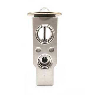
Expansion valve is used to control the amount of refrigerant entering the evaporator. It has a small hole which lets the valve to spray the refrigerant. As the high pressure refrigerant passes into the expansion valve, both pressure and temperature drop and it is sprayed into the evaporator in a misty form.

Evaporator:


Evaporator acts like a radiator. The low pressure, low temperature refrigerant in gaseous form passes through the coils inside the evaporator. A blower fan pulls the heat out from inside the vehicle cabin and blows the warm air over the evaporator. Since the temperature inside the evaporator is lower, it absorbs the heat from the blower and leaves behind cooler air. This cooled air is circulated into the car cabin. The refrigerant which is hot now and in gaseous form is circulated back to the compressor and the cycle keeps repeating.

Blower


Refrigerant:

Freon-R12 was used commonly but due to its damaging effects on the ozone layer, manufacturers have replaced it with R-134a. 


Tuesday, 5 May 2020

Car Sales Plunge to Zero in April 2020

As India announced nationwide lockdown from 24th March 2020 and with the restrictions covering the entire month of April, grim reports for automobile manufactures came out as zero sales were recorded in the month of April due to the closure of showrooms and manufacturing facilities. Big companies such as Maruti Suzuki, Hyundai and Mahindra registered zero domestic sales.


Thanks to the resumption of port operations, Maruti Suzuki was able to export 632 units abroad. The export numbers for Hyundai and Mahindra stood at 1341 and 733 units respectively for the month of April.

However, Mahindra and Mahindra did witness some tractor sales because dealers were open partially in the last month. It recorded 4716 tractor sales in India, down by 83% as against 27,495 units sold in April 2019. Mahindra's farm equipment sector exported 56 tractors last month, down by 95% compared to 1057 units exported in the same month last year.


S.No.
Manufactures
April 2020
April 2019
1
Maruti Suzuki
0
1,31,385
2
Hyundai
0
42,005
3
Mahindra and Mahindra
0
18,901
4
Toyota
0
10,112
5
Ford
0
6,515
6
Volkswagen
0
1,995
7
Honda
0
11,272
8
Tata
0
12,695
9
Renault
0
6,256
10
Nissan
0
2,027
11
Skoda
0
1,126

With lockdown extended till May 17, there is little to no hope of reviving the automobile sector in the coming months. Due to low earnings, demand especially among the middle income customers might fall sharply. Government can intervene by reducing GST for some months.  

Thursday, 13 February 2020

BS 6 vs BS 4 Emission Norms Comparison

Most of us would have seen cars coming out in 2020 with 'BS 6' label on it. What does it actually mean? To explain it in a common man's terms, it means the emission laws imposed on a vehicle to regulate the pollution levels due to the burning of fossil fuels.

The government of India has put forth pollution regulations known as Bharat Stage Emission Standards (BSES). It mandates all the vehicle manufacturers (two and four wheeler) to manufacture vehicles based on the emission standards set by the government. From April 1, 2020 all the vehicles manufactured, sold and registered in India should comply with the BS 6 (Bharat Stage 6) emission standards.

This article is about the differences between the old standard BS 4 and the upcoming emission norms BS 6.

The BSES introduced the first emission norms in India in the year 2000 with the name 'India 2000', which can also be considered as BS 1. Five years down the line, BS 2 was introduced in 2005, followed by BS 3 in 2010 and BS 4 in 2017 with stricter emission norms. BS 5 has been skipped to achieve the climate control goals set for India in the Paris Climate Accord in 2016.

All the BS norms are in line with the Euro norms that is followed in European countries.

Petrol engine:

Norms
NOx (mg/km)
PM (mg/km)
CO (mg/km)
HC (mg/km)
BS4
80
-
1000
100
BS6
60
-
1000
100

Diesel engine:


Norms
NOx (mg/km)
PM (mg/km)
CO (mg/km)
HC+ NOx (mg/km)
BS4
250
25
500
300
BS6
80
4.5
500
170

NOx - Nitrogen oxide
PM- particulate matters
CO- carbon monoxide
HC- hydrocarbons
mg/km- milligram per kilometer

Automatic Headlamp On (AHO):

One of the notable changes in BS 6 is automatic headlamps on feature which is enabled in two wheelers to keep the headlights on all the time to ensure pedestrian safety.


Wednesday, 12 February 2020

Exit Warning System

Exit warning system warns the occupants in a car of the vehicles approaching from behind as they open the doors of their car. This system scans the area behind the parked vehicle and keeps the doors locked unless the coast is clear to protect other passing vehicles.

Audi had first introduced this feature in it's A4 and Q7 models in 2015. It would only alert the driver of any approaching vehicles through warning lights. In 2018, Audi upgraded the technology by physically blocking the doors until the approaching vehicle passes by. It doesn't lock the door forever but for a mere 0.8 seconds which should be enough for a vehicle to pass by. It was installed in A8 model.


Wednesday, 5 February 2020

Mercedes GLA 2020

Mercedes Benz is set to launch the all new GLA-class in the compact luxury SUV segment. It is expected to hit the Indian market in June 2020. It will have petrol and diesel engines complying to BS6 norms. The prices are expected to start at 43 lakhs INR. The good news for the customers is that bookings are open and preorders can fetch a discount of 1 lakh INR.


There are minor changes in the overall design which doesn't much change the looks compared to it's predecessor. The wheelbase has been increased and the overhangs have been shortened to provide more interior space. It will be 30 mm wider. 104 mm has been added to it's height and 15 mm reduced in length. Despite the reduction in length, legroom won't be affected as the wheelbase has been increased.

Mercedes has added some new safety features:

  • Sensors to detect pedestrians around the car to alert the driver.
  • Exit warning system to keep the doors of the car locked unless the lane besides the vehicle is clear and no vehicles or cyclists are approaching the car.
  • Active Break assist system to automatically apply brakes in the event of an impending collision.
When launched the GLA-class will give competition to the BMW X1, Volvo XC40 and Audi Q3.


Engine specs:

GLA 200 will come with a 1.3 liter turbocharged petrol engine capable of producing 161 hp and 250 Nm torque. It will be coupled with 7 speed dial cluth transmission.

GLA 35 4MATIC AMG will come with a 2 liter turbocharged petrol engine churning out a power of 302 hp and 400 NM torque. It will come with an AMG speedshift 8 speed dual clutch transmission.


Sunday, 23 June 2019

Electric cars better than fossil fuel cars?

Rising population, better road infrastructure, increasing rail, air and water connectivity and who knows
so many reasons, but more and more people are traveling around the world. The transportation sector
is contributing to almost a quarter of the total greenhouse gas emissions around the globe. One may
argue that shifting to all electric vehicles can reduce the impact on climate change, if not solve it.
According to the Paris climate agreement of 2016, the target is to run 100 million electric vehicles
(EVs) on the road by 2030. As of 2017, it is around 3.1 million EVs.


How much clean is an Electric Vehicle?

A car that runs completely on electricity does not produce any emissions per se, but the source from
which electricity is produced can contribute to emissions. Electricity produced from renewable sources
such as wind and sun virtually produces no emissions. But those produced from coal, oil and natural
gas does contribute a significant amount of pollutants.

Increase in number of EVs will result in increased demand of electricity which in turn will lead to
higher demand for oil. This may result in higher emissions.

To reduce the pollution levels from electrification, stricter policies have to be implemented. Investment
in renewable sources of energy is the need of the hour.

China leading the way:

The share of renewable sources for electricity production has increased significantly over the past few
years. China is leading the way in renewable energy. It is the world’s largest producer and exporter of
solar panels, wind turbines, batteries and electric vehicles.

In 2017, China’s renewable energy comprised 36.6% of its total installed electric power capacity, and
26.4% of its total power generation. The vast majority of its renewable sources is hydroelectric.

China is also the number one market for electric vehicles. The sales surged by 72% in 2017, pushing
their total ownership to over 1 million EVs. The country is also driving the growth in bus and two-
wheeler sector, holdin 99% of the world’s total stock.

Electric vehicles future in India:

India has been pushing to make plans for a major shift towards electric vehicles by 2030. Being a
member of Electric Vehicles Initiative (EVI), India plans to have EVs contribute to 30% of all vehicle
sales by 2030.

Looking at the ground reality, the plan seems to have a lot of dead ends which will hinder India’s goal
of achieving the target.

70% of India’s electricity production comes from coal. Coal being the main source of power, increase
in EVs will result in need for more coal to reach the power demand. This will dent India’s goal to cut
the emissions.

India is on its way to roll out BS-VI emission norms in 2020. Vehicle manufacturers will be recalibrating
vehicles to meet the norms and hence they will be left with lesser investment for EVs.

High cost of EVs and poor public charging infrastructure makes it less appealing to the already
reluctant customers to buy EVs.


Unless the government comes with a better policy to improve the infrastructure and to provide
incentives to the EV manufacturers with low taxes and other benefits, it is difficult to provide an
affordable range of EVs to Indian customers. Investment in renewable sources of energy will also
help in cutting the emissions.